Download
1 / 33
330 likes | 553 Vues
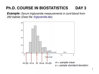
0.25 m m CMOS electronics in CMS. APV25 - readout chip for Si Tracker production wafer testing status yield experiences production QA results MGPA - M ulti- G ain P re- A mplifier chip for ECAL prototype design & performance current status. APV25.

E N D
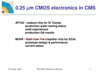
0.25 mm CMOS electronics in CMS APV25 - readout chip for Si Tracker production wafer testing status yield experiences production QA results MGPA - Multi-Gain Pre-Amplifier chip for ECAL prototype design & performance current status UK CMS Collaboration Meeting
APV25 128 channel chip for analogue readout of AC coupled Si sensors Main features 50 nsec. CR-RC amplifier 192 cell pipeline (up to 4msec latency + buffering) peak/deconvolution operating mode peak mode -> normal CR-RC pulse shape deconvolution -> single bunch crossing resolution I2C slow control interface: bias registers, mode, latency …. On-chip CAL circuit: amplitude and delay programmable Rad-Hard: >10 Mrads pipeline 128x192 APSP + 128:1 MUX 128 x preamp/shaper 7.1mm control logic bias gen. FIFO pipe logic CAL 8.1 mm APV O/P Frame Peak Decon. digital header 128 analogue samples UK CMS Collaboration Meeting
Wafer Testing Objective Identify faulty chips at wafer level with high level of fault coverage -> maximize yield of multi-chip hybrids The task 360 viable sites/wafer ~ 73,000 chips required (+ spares) => ~ 300 wafers (yield dependent) 2 wafer/day throughput required to keep up with module production generate wafer map for cutting co. store all test information in database wafer id, chip# 8 inch APV wafer UK CMS Collaboration Meeting
Wafer Test Hardware Micromanipulator 8 inch semi–automatic probe station VME based ADC (8 bits) RAL SeqSi 40 MHz CK/T1 CERN VI2C I/F PC controls both DAQ (VME) & probe-station (RS232) UK CMS Collaboration Meeting
Wafer Test Software LabView based, aim for comprehensive fault coverage digital: chip addressing, stuck bits, pipeline control logic, ….. analogue: supply currents, all channels pulse shapes, all pipeline locations OK, noise, …… green lights => all tests passed calibration pulse shapes – all chans power supply currents calibration gain channel noise channel pedestals pipeline pedestals (128 x 192) UK CMS Collaboration Meeting
Wafer Test Software (2) individual chip test subvi called by supervisory vi controls probe station movement generates pass/fail wafer map time to test 1 chip ~70s => ~ 7 hrs/wafer => 2 wafers/day no.of good chips total available on wafer (360) high yield wafer = yield UK CMS Collaboration Meeting
Wafer Test – Yield Experiences Lot 1 date lot # wafers yield [%] (long story, cut short here) problems seen as soon as production started circular failure patterns => processing problem (acknowledged by manufacturer) other HEP designs also experiencing similar problems 2002 actions to understand unsuccessful 2002 2003 Lot 3 major investigation launched February this year (following Jan deliveries) - wafers from all problem lots sent for failure analysis (FA) - modified wafer test software – try to localize failures within chip - weekly phone conference set up involving manufacturer’s FA teams on 2 sites, IC & RAL, CERN coordinating team UK CMS Collaboration Meeting
Example Fault Diagnosis – Lot 4 this wafer showed high power consumption failures – liquid crystal technique showed hotspots in pipeline control logic area non-contacting vias found => transistors which should be off can float to on condition => high power consumption separation between metal layers close to maximum allowed => points to possible problem with Inter-Level Dielectric (ILD) layer thickness control (etch time is fixed) high ILD thickness and non-contacting vias also found on samples from other low-yield lots UK CMS Collaboration Meeting
FA Conclusions (mid 2003) High ILD thickness appears to be common feature in low yield lots (APV25 and other designs) High Q2 (capacitor metal) coverage, non-uniform metal layer coverage in some designs thought to be contributing factor (all metallization issues). Solution process has been tweaked (!!) to achieve lower ILD thickness for APV runs Lessons learnt main one: good relationship with responsive manufacturer extremely valuable without we would still be in the dark – and still getting variable yields debugging these kind of problems requires expert knowledge of process and special equipment (hot-spot analysis, de-layering, electron microscopy) UK CMS Collaboration Meeting
2002 very high yield since process modified to reduce inter-level dielectric thickness looks like problem solved 2003 Wafer Test Yields Summary – to date date lot # wafers yield [%] 184 wafers (excluding lots 1, 2 & 4 - 8) , ~ 53,000 good chips UK CMS Collaboration Meeting
Wafer Test Results Analysis Example (1) Peak Mode Deconvolution average pulse shapes for all pass chips (lots 1 – 5) normalised to max. pulse height (~ 13,000 chips) shows good pulse shape matching for all chips even without individual tuning (same set of bias parameters for every chip) not much wafer or lot dependence Lot 1 Lot 1 Lot 2 Lot 4 Lot 2 Lot 4 Lot 3 Lot 5 Lot 3 Lot 5 UK CMS Collaboration Meeting
Wafer Test Results Analysis Example (2) Supply Currents Channel Noise Channel Gain ~ small spread within a lot (~ 24 wafers) lot averages -> not much difference between lots conclusions: close wafer:wafer and lot:lot matching UK CMS Collaboration Meeting
QA procedures (IC & Padova) Objective perform more detailed tests (including irradiation) on chips sampled from probed wafers after dicing. Cutting company picks 3 chips and returns them to us (wafer test limited – time, electrical environment noisy, irradiation not feasible) QA sample size initially 100% (chip from every wafer) decreasing to ~ 20% as confidence established Procedure measure … irradiate (10 Mrads) … re-measure … … anneal (1 week @ 100oC) … re-measure 25 mm UK CMS Collaboration Meeting
QA Irradiation Setup Identical facilities at Padova & IC X-ray spectrum peak ~ 10 keV (Vtube=50 kV, Itube=10mA,150mm Al filtration) dose-rate calibration performed using Si diodes, overall accuracy ~ 10% relative accuracy (Padova:IC) ~ 1% 10 Mrads takes ~ 14 hours UK CMS Collaboration Meeting
Chip QA measurement: Pre-rad UK CMS Collaboration Meeting
Chip QA measurement: 10 Mrads + Anneal UK CMS Collaboration Meeting
Example Chip QA measurement: Noise decon (added C) peak (added C) decon baseline peak baseline conclusion: no QA problems observed so far UK CMS Collaboration Meeting
APV Conclusions Wafer probing production wafer probe test setup working well throughput 2 wafers/day ~ 53,000 good chips available for module production (~ 73,000 needed) analysis of test data shows good matching between chips, wafers and lots yield problems observed on some lots now believed understood and solved QA measurements automated measurement setup and protocol developed measurements pre-rad, after 10 Mrads, after anneal good results from sampled lots so far, no surprises UK CMS Collaboration Meeting
The MGPA ECAL readout chipfor CMS MGPA New 0.25mm VFE chip for ECAL Prototype results as presented at recent LECC conference Minor modifications to prototype -> new version just submitted for engineering run Multi–Gain Pre-Amplifier - 0.25 mm CMOS chip for CMS ECAL 9th Workshop on Electronics for LHC Experiments, Amsterdam, 2003 UK CMS Collaboration Meeting
New ECAL VFE (Very Front End) Architecture PbWO4 scint. 12 General approach use multiple gain ranges -> high resolution with only 12 bit ADC only transmit value for highest gain channel-in-range => have to take decision on front end Previous architecture range decision taken in preamplifier (complex chip), followed by single channel commercial ADC New architecture 3 parallel gain channels (MGPA), multi-channel ADC, range decision taken by logic in ADC chip use 0.25 mm CMOS to take advantage of: radiation hardness system simplifications: single 2.5V supply, power savings short fabrication turnaround time, high yield, cheaper Short timescale for development design begun mid 2002, submission early 2003, die received May 2003, packaged die since August LOGIC 12 bits 6 2 bits 1 opto-electric barrel: APD endcap: VPT MGPA Multi-channel ADC UK CMS Collaboration Meeting
MGPA Target Specifications Barrel/Endcap read out using APD/VPT different capacitance and photoelectric conversion factors spec. review -> 3 gain ranges sufficient to deliver required performance -> MGPA design easier Additional calibrate feature -> not precision but allows charge injection to each front end chip Vpk-25 Vpk UK CMS Collaboration Meeting
MGPA Architecture 1st stage RFCF = 40 nsec. (avoids pile-up) choose RFCF for barrel/endcap => 1 chip suits both RF dominant 1st stage noise source => independent of CIN 3 gain channels 1:6:12 set by resistors (on-chip) for linearity differential current O/P stages external termination 2RICI = 40 nsec. => low pass filtering on all noise sources within chip calibration facility prog. amplitude I2C interface to programme: output pedestal levels enable calibration feature cal DAC setting i I2C and offset generator RI CI i VCM RG1 RI i DAC RI CI VCM RG2 RI ext. trig. CCAL charge amp. RI CI VCM RG3 I/P RI diff. O/P stages gain stages RF CF RFCF UK CMS Collaboration Meeting
Chip Layout layout issues gain channels segregated as much as poss. with separate power pads -> try to avoid inter-channel coupling lots of multiple power pads die size ~ 4mm x 4mm packaged in 100 pin TQFP (14mm x 14mm) offset gen. I2C diff. O/P stage high gain stage diff. O/P stage mid gain stage 1st stage low gain stage diff. O/P stage UK CMS Collaboration Meeting
Test Setup priority given to measurements for barrel gain (60 pC fullscale) True rms milli-voltmeter Pulse Gen. Programmable Attenuator Scope diff. probe MGPA test board UK CMS Collaboration Meeting
Pulse Shape Measurements low gain range mid gain range high gain range differential O/P signals (diff. probe) 0 – 60 pC, 33 steps saturation in mid and high gain ranges but no obvious signs of distortion in lower gain ranges => effective gain channel segregation in layout gain ratios 1 : 5.6 : 11.3 (c.f. 1 : 6 : 12) Volts linear range time [nsec] UK CMS Collaboration Meeting
Linearity: High Gain Channel linearity within (or close to) spec for a range of gain stage bias currents => not v. sensitive to bias conditions linearity [% fullscale] spec. similar results for mid and low gain channels relative signal size 5.4 pC Linearity [% fullscale] = peak pulse ht. – fit (to pk pulse ht) X100 fullscale signal UK CMS Collaboration Meeting
Pulse Shape Matching Vpk Vpk-25 pulse shapes for all 3 gain ranges (11 steps / range) all 33 pulse shapes overlaid normalise to max pulse ht. pulse height [Volts] time [nsec.] pulse shape matching important within and across gain ranges to quantify use pulse shape matching factor, PSMF = Vpk-25 Vpk UK CMS Collaboration Meeting
Pulse Shape Matching pulse shape matching close to spec. (+/- 1%) spec. pulse shape matching [%] relative signal size [1=fullscale] Pulse shape matching [%] = (PSMF – Average PSMF) x 100 Average PSMF (Average PSMF = average over all pulse shapes and all 3 gain ranges) UK CMS Collaboration Meeting
Noise within spec. < 10,000 (barrel) < 3,500 (endcap) weak dependence on input capacitance as expected higher electronic noise not significant for low gain range gain stage noise dominates for this range estimated errors: ~ 10% high and mid-gain ranges, ~20% low gain range UK CMS Collaboration Meeting
Radiation Tests low mid high pre-rad 5 Mrads ~ 3% reduction in gain after 5 Mrads (2 x worst case) no measurable effect on noise (10 keV X-rays (spectrum peak) , dosimetry accurate to ~ 10%, doserate ~ 1 Mrad/hour, no anneal) UK CMS Collaboration Meeting
On-chip Calibration Feature external edge trigger Volts ext. 10pF MGPA I/P I2C simple DAC allows programmable (I2C) amplitude charge injection -> range of signal sizes for each gain range external trigger required allows functional verification during chip screening and in-system nsec. UK CMS Collaboration Meeting
MGPA Conclusions First iteration successful Analogue performance good gain, linearity, pulse shape matching, noise all within or v.close to spec. rad-hard as expected System tests multiple chips mounted on VFE cards, with multi-channel ADCs used with APDs/crystals in beam test -> encouraging performance Next iteration minor design changes pinout (requested to assist VFE card layout) I2C register default values (chip biases up close to nominal operating point on switch-on) current reference to bias generator included on-chip Already submitted(17th Nov.) for engineering run expect wafers early in New Year -> enough chips for Supermodule calibration in 2004 UK CMS Collaboration Meeting
Deep Sub-Micron Future* 0.25 mm CMOS turned up just in time (~1998) – where would we be without it? in CMS everything (I think) from HCAL in now 0.25mm - Pixel, Tracker, ECAL readout and control ASICs 0.25mm technology will not be around forever (maybe until 2007?) 0.13mm next logical step (have to follow industry – skip 0.18mm) need special relationship with (and goodwill of) technology supplier prototypes -> production NOT a smooth ride (e.g. APV yield experiences) understanding yield issues requires close collaboration with foundry HEP projects need relatively few wafers c.f. foundry capacity 0.13mm offers possible improvements in: power reduction: most of tracker material budget electronics related (power cabling, cooling) higher speed and circuit density, more rad-hard, …. also challenges -> R&D required circuit techniques to cope with reduced supply headroom (1.3V) radiation effects (ionizing and SEE) generating and characterising digital circuit libraries (and analogue?) modelling more complicated (more metal layers -> complex parasitic couplings) undisputable statement: LHC (and future HEP) experiments not possible without ASICs *see Sandro Marchioro’s talk at LECC’03 LHC electronics workshop UK CMS Collaboration Meeting