CMS Muon Electronics
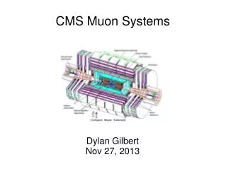
CMS Muon Electronics. Flavio Loddo (on behalf of CMS) I.N.F.N. Bari. CMS Muon Electronics. Barrel (0 < < 1.2): Drift Tube chambers (DT) Resistive Plate Chambers (RPC) Endcap ( 0.9 < < 2.4): Cathode Strip Chambers (CSC) Resistive Plate Chambers (RPC). CSC Electronics.

CMS Muon Electronics
E N D
Presentation Transcript
CMS Muon Electronics Flavio Loddo (on behalf of CMS) I.N.F.N. Bari ACES 2007 CERN 19-21 March 2007 F. Loddo I.N.F.N. Bari
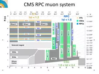
CMS Muon Electronics Barrel (0 < < 1.2): Drift Tube chambers (DT) Resistive Plate Chambers (RPC) Endcap (0.9 < < 2.4): Cathode Strip Chambers (CSC) Resistive Plate Chambers (RPC) ACES 2007 CERN 19-21 March 2007 F. Loddo I.N.F.N. Bari
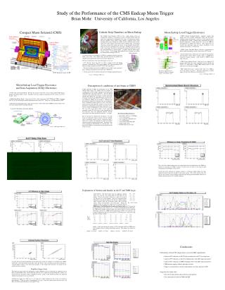
CSC Electronics • No modifications on the detector • Modify only the electronics for trigger path • (Darin Acosta’s talk) ACES 2007 CERN 19-21 March 2007 F. Loddo I.N.F.N. Bari
DT Electronics • Bunch spacing = 12.5 ns the trigger signal cannot be uniquely associated to its parent BX, because electrical propagation time along 2.5 m anode wire is comparable to BX spacing • The system can run at 40 MHz, but can only tag time frames of two BXs. • Possible solutions to recover BX identification capability (all must be evaluated in terms of practical feasibility, performance and costs: • Signal readout at both wire ends OR Readout of the signal reflected by the wire open end (more cables) • The 2 super-layers in the same chamber are clocked with two de-phased40 MHz clocks: 1 super-layer latch on even BXs and the other on odd BXs. • integrate RPC (good time resolution BX identification) and DT (excellent determination of muon tracks parameters). The drawbacks are less robustness and lower acceptance with respect to two complementary trigger systems • Bunch spacing = 25 ns or 50 ns no problem with the implemented system ACES 2007 CERN 19-21 March 2007 F. Loddo I.N.F.N. Bari
RPC Electronics Initial system: Full barrel Endcap: 3 stations , < 1.6 • On-chamber electronics: Front-End Boards • Tower electronics: Link Boards, Control Boards and RPC Balcony Collector • Counting Room : Trigger Electronics ACES 2007 CERN 19-21 March 2007 F. Loddo I.N.F.N. Bari
RPC Electronics • The Front-End Boards are based on a chip designed in AMS 0.8 m BiCMOS Tech. • Fast amplifier + Zero-Crossing Discriminator Time walk ~ 1 ns • Expected strip rate in LHC < 5 kHz/strip (100 kHz/strip in Endcap > 1.6 region) • Maximum Front-End sustainable rate: ~ 10 MHz can be used in SLHC • Expected neutron fluence in LHC: < 1010 cm-2 (1011 cm-2 in high region) • Irradiation tests: • Neutron fluence ~ 1.0 x 1012 cm-2( > 10 years of LHC operation in the CMS muon end-cap region) • no SEL detected • Average time between SEU < 1 h/Chip (False hit rate < 0.27 mHz/chip) The on-chamber RPC Electronics can operate in SLHC ( < 1.6) (more investigations needed for the high region) ACES 2007 CERN 19-21 March 2007 F. Loddo I.N.F.N. Bari
RPC (Detector Upgrade) • No evidence of detector ageing up to 10 years of LHC operation (results of GIF tests) • Rate in the < 1.6 region of SLHC 100 Hz/cm2 (maximum) still compatible with detector performance • However, present technology was not certified for > 1.6region and therefore is not suitable for SLHC • High rate decrease the charge in the detector ~ 1 pC few tens of fC • Possible candidates for SLHC high region: • Evolution of RPC (thinner gap) • Thin gap chambers (employed in ATLAS high region) • GEM (employed in LHCb) ACES 2007 CERN 19-21 March 2007 F. Loddo I.N.F.N. Bari
RPC (ElectronicsUpgrade) • Present Front-End not suitable: develop new circuit • Rad-tolerant technology (0.13 m) • Higher gain • Preserve the fast slope of input signal for fast timing • Low time walk ACES 2007 CERN 19-21 March 2007 F. Loddo I.N.F.N. Bari
RPC Trigger Electronics • Bunch spacing = 12.5 ns cannot be treated by the present Link System and Trigger system Electronics: full re-design • Bunch spacing = 25 ns RPC Trigger Electronics OK, but possible DAQ overload • Bunch spacing = 50 ns RPC Trigger Electronics OK, but all firmware must be re-designed • Wait for LHC turn on: • background impact • trigger efficiency (higher pt eff. curves are less sharp) • compression strategy to be studied ACES 2007 CERN 19-21 March 2007 F. Loddo I.N.F.N. Bari
Conclusions • DT system can operate without modifications if Bunch Spacing = 25 or 50 ns • DT cannot work if Bunch Spacing = 12.5 ns: different solutions are under evaluation • RPC detector can operate in the low region with the same FE • Detector and FE upgrade is needed for > 1.6 region • RPC Trigger Electronics can operate with some modifications if Bunch Spacing = 25 or 50 ns • RPC Trigger Electronics must be fully re-designed if Bunch Spacing =12.5 ns ACES 2007 CERN 19-21 March 2007 F. Loddo I.N.F.N. Bari