CMS Muon Systems
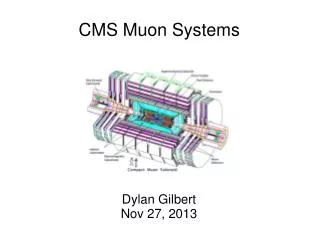
Dylan Gilbert Nov 27, 2013. CMS Muon Systems. Location, Size, and Structure, Briefly. 4 layers outside the solenoid. Inconsistent field (unlike constant 4T inside solenoid).

CMS Muon Systems
E N D
Presentation Transcript
Dylan Gilbert Nov 27, 2013 CMS Muon Systems
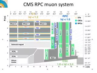
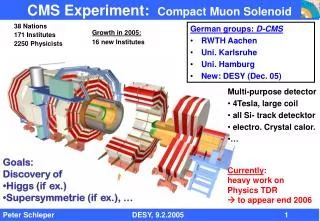
Location, Size, and Structure, Briefly • 4 layers outside the solenoid. • Inconsistent field (unlike constant 4T inside solenoid). • Layers interleaved with the magnet yoke, an iron structure that uses its high magnetic permeability to capture and return the solenoid's field. • Different design (in fact, different fundamental detection units) between barrel and endcap. • Most of the active volume of the detector. • More than 4 meters thick on all sides. (Solenoid is about 13m long x 6m diameter.)
Muon System Goals • pT uncertainty for 10 GeV of ~1% in combo with tracker. • pT uncertainty for 1 TeV of ~10%. • At 1 TeV, spatial resolution in bending plane of 1 mm, non bending plane 10 mm. • Allow for measurement of muons within jets (*b-tagging*). • At least 16λ for all |η| < 2.4 (contain the muons). • Trigger efficiently on pT ≥ 1 GeV muons for |η| < 2.1. • At least 99% confidence charge assignment up to 7 TeV. • Response on the order of the bunch interval (25 ns). • Cost-control important, considering large size. • In general, outstanding measurement of muons was CMS' driving priority from the outset.
Momentum Measurement Contribution • The muon system gets p from the bending angle of the muon track in the B field, so a small bending angle leads to larger relative uncertainty in the momentum. • At low pT (< 200 GeV), not a good measure, due to energy loss and multiple scattering.
Barrel vs. Endcap Resolution • Muon system in combo with tracker similar at high p in barrel and endcap. • Determined by multiple scattering at low p, measurement uncertainty for high p, and multi-scattering higher for endcap.
Matching Muons to Jet Tracks • Even with a jet of tracks around, muon tracks from the muon system are matched with remarkable accuracy to track in the tracker.
Material Thickness • Muons well contained in barrel. • More material in endcap.
Drift Tubes • Chosen when muon flux is small, and B field is relatively consistent; |η|<1.4. • 4cm wide aluminum container of gas with a taut positively charged wire in the center that collects electrons knocked off gas atoms by passing muons. • Measure a 2D point by using time delay of electrons drifting to the wire with a known drift velocity, and the point on the wire perpendicular to drift direction where the electrons arrived. • Each drift tube chamber in detector layers 1-3 is 12 planes of tubes, with two groups (“super layer”) of 4 r-Φ planes surrounding a group of 4 z planes (no z in the 4th layer's chambers). • Each station produces a muon motion vector with Φ resolution 0.1mm in location and 1mrad in direction. Poor time resolution (~400 ns).
Cathode Strip Chamber • Chosen where neutron background is high, muon flux is large, and B field is relatively uneven; 1.4 < |η| < 2.4. • Consist of a grid of positively charged wires and negatively charged strips in gas. Electrons knocked off gas land on the wire, causing an immediate response in the nearby positive strips, an immediate rough 2D position (no drift calculation needed). Closely spaced wires also minimize time the electrons spend drifting to wire. • A CSC produces a muon vector with position resolution 0.2 mm and Φ direction resolution 10 mrad, but can produce a coarser measurement very quickly.
Resistive Plate Chamber • Complementary to DTs and CSCs. • Good time resolution (~3 ns) and fast response, less good spatial resolution (but quick!). • Cheap, so they can be sufficiently granular to give a quick and dirty template-based pT reading for triggering. • Unambiguously associate muon with a bunch crossing and give quick pT/position, but leave the precise measurements to DTs/CSCs (to which they are coupled in a 1:1 or 2:1 ratio). • Located at |η| < 2.1, throughout the barrel and the outer portion of the endcaps. • Once again, signal is electrons knocked off a gas, in this case drawn to metal strips surrounding charged plastic electrodes. • Single layered but highly segmented and time resolved nature makes them vulnerable to different background from DT/CSC.
The Barrel • DT-RPC units arranged in 4 layers called stations, in 5 wheels. • Each wheel is divided into 12 sectors covering 30o each. • 3 inner layers have 12 chambers each, 1 per sector. The fourth layer has 2 chambers in the top and bottom sectors, for 10(1)+2(2) = 14 chambers in the 4th layer. • Chambers are staggered layer-to-layer so that a muon hits at least 3, even at the edge of a sector. • In the two inner layers, each DT is between two RPCs. In outer layers, each DT has only a single RPC on the inside.
The Endcap • 4 disks of CSC-RPC pairs, with the closest to the primary vertex having 3 concentric rings and the 3 further have 2 rings each. • Staggered in Φ to avoid muons slipping through cracks. • In disks 2-4, the outer ring has 36 chambers covering 10o each and the inner has 18 covering 20o each. • 10cm thick iron plates at the extremes of the detector protect the endcaps from beam axis backsplash. • The B field in layers 2-4 is weak (< 1T) and highly non-uniform, making layer 1 (>3T, axial) by far the most important for measuring momentum of endcap muons.
Charge Assignment • Thus, as hoped for a prioritized system, all major design goals were met.