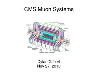
CMS Muon System
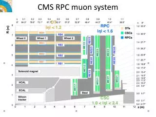
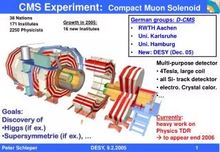
CMS Muon System. Guenakh Mitselmakher University of Florida. Muon detectors. Barrel DTs and RPCs. Endcap CSCs and RPCs. - 250 DTs coupled with RPCs - 468 CSCs in 4 stations (ME4/2 descoped) - 3 stations of Endcap RPCs (REs) ( 4 th RE station and η > 1.6 descoped).

CMS Muon System
E N D
Presentation Transcript
CMS Muon System Guenakh Mitselmakher University of Florida
Muon detectors Barrel DTs and RPCs Endcap CSCs and RPCs - 250 DTs coupled with RPCs - 468 CSCs in 4 stations (ME4/2 descoped) - 3 stations of Endcap RPCs (REs) ( 4th RE station and η> 1.6 descoped)
Offline Muon Reconstruction Expected Performance Muon+Tracker (“GlobalMuonReconstructor”) Standalone Muon CMS AN 2005/010
Main Components of the CMS Muon System • Barrel Drift Tubes (DTs) • Precision measurement and trigger • Barrel Resistive Plate Chambers (RPCs) • Trigger • Endcap Cathode Strip Chambers (CSCs) • Precision measurement and trigger • Endcap RPCs • Trigger • Alignment (Barrel, Endcap and Link)
4 3 5 2 6 1 7 12 8 11 9 10 Barrel Muon System The Barrel Muon system: 250 chambers in 7 flavors: 60 MB1 3SL 2 RPC ~2.0 x 2.54 m2 960kg 60 MB2 3SL 2 RPC ~2.5 x 2.54 m2 1200kg 60 MB3 3SL 1 RPC ~3.0 x 2.54 m2 1300kg 40 MB4 2SL 1 RPC ~4.2 x 2.54 m2 1800kg 10 MB1 2SL 1 RPC 10 MB2 2SL 1 RPC 10 MB3 2SL 1 RPC F SL SL Honeycomb F SL DTs assembled at four sites: Aachen, Madrid, Padova, Torino All DTs are at CERN
42 mm S g C s a b 13mm W b/a ~ .65 Basic cell structure of the Drift Tubes continuous lines represent electrodesdotted lines represent equipotential surfaces the position of the s equipotential depends on the cell geometry ( on the strip width and on the wire radius) Vw-Vs determine the gas gain: a gain of ~ 10^5 determines the position of the s equipotential to be ~ 2.5 mm from the wire Equipotential g is almost independent of the Voltages of s and c Vc ( and Vs) generate in the region between c and g ( and between g and s ) an electric field between 1 and 2 KV/cm to saturate the drift velocity
CMS RPCs : Barrel 60 sectors RB4 120 chambers (2 double gaps per chamber) RB3 120 chambers (2 double gaps per chamber) RB2 60 chambers (2 double gaps per chamber) + 60 chambers (3 double gaps per chamber) RB1 120 chambers (2 double gaps per chamber) BW FW Double gap
STATUS OF DT AND RPC PREPARATION All DT (250 + 12 spare) are at CERN All the Minicrates (250) are at CERN 104 to be installed in 2006/2007 97 DT are certified 7 under certification 77 DT are certified (2 months under HV + cosmic run) and equipped with MCrate 20 DT are certified and to be equipped with MC 24 RPC out of the 208 to be installed are missing (at CERN by November to be coupled to 12 DT) 26 DT are already coupled to 52 RPC and ready on the transport frames (the max affordable is 34, in October) BMU ARE READY FOR INSTALLATION………………………
end 2006 UX end 2006 SX end 2006 beg,07 SX in 2007 UX INSTALLED 42 YB+1 42 YB+2 40 YB0 13 YB-1 9 YB-2 8 YB+1 8 YB+2 8 YB0 8 YB-1 8 YB-2 2 29 5 28 SX 146 35 16 28 24 DTs and Barrel RPCs: STATUS OF INSTALLATION DT+RPC 64 chambers to be installed in SX 40 chambers to be installed in UX total is 104
DTs: INSTALLATION AND COMMISSIONING TIME EXPERIENCE on surface: Installation of 32 chambers ~ 2 weeks Service connect.+ commissioning ~ 6 weeks ( two teams in parallel) The rate for Install.+commiss. ~ 4 chambers /week EXPECTATION: 64 DT+RPC install.+commissioning on surface 16 weeks Cabling (two teams in parallel) 5 weeks/wheel 40 chambers in UX ( lower rate) 12 weeks The total is 8 working Months start November 2006, end June 2007 Continuous work, assuming no interference or problems Tight schedule, but possible to finish on time for the commissioning run
Aim Jun 04 Achieved : Aug 06 11 10 Barrel MU: GOAL AND RESULTS FROM MAGNET TEST/COSMIC CHALLENGE
Barrel Detectors and Alignment: first conclusions from MTCC 1) The DT trigger has shown to be highly versatile and configurable, exploiting a wide range of rates DT + BRPC generated more than 10M events with magnet on and of in 5 days from Aug 24 to 28th. 2) The trigger has proven to be very clean ,Synchronization is easy. 3) First analysis confirms that RPC are unaffected by B-Field. No problem with DTs, even in the areas sensitive to B in the highest Field region (MB1/2). 4) The Alignment was able to measure the bending of YE+1 (value as expected) and the relative displacement of the Tracker versus MU
Mu Ali. Meas. the distance between Tracker and Link disk on YE+1 R/PHI position of chambers with respect to the nominal as measured by tracks and photogrammetry. Data from PG provide an excellent starting point! Nose moves in by 16 mm TRACKS SURVEY Outer rim moves out by 6 mm (a top/bottom asymmetry is observed)
Dphi12 Dphi12 Dphi 12 B = 0 B 3.8T 1 2 3 Dphi 23 Dphi23 Dphi 23 Dphi 12 = deflection from 1 to 2 Dphi 23 = deflection from 2 to 3
RPC Majority: 6/6 (RBC = RPC Barrel Chambers) MTCC…RBC trigger • 5/6 - trigger rate ~30 Hz per wheel • 6/6 - trigger rate ~13 Hz per wheel • DT occupancy with RPC trigger
MTCC Number of clusters Cluster size Combined offline RPC (green) and DT event
MTCC. Barrel Muons: SUMMARY AND PERSPECTIVES DT and RPC Triggers are coherent, stable and precise The effect of B Field on DT is as expected The first test of Alignment system looks positive Position of the chambers from Tracks are in excellent agreement with photogrammetry Cosmic tracks and Alignment system will allow DTs to be well prealigned in time and space in the cavern before the Pilot Run
Endcap Muons: CSC Layout • 468 CSCs, not counting ME4/2 • 144 Large CSCs (3.4x1.5 m2): • 72 ME2/2 chambers • 72 ME3/2 chambers • Small CSCs (1.8x1.1 m2): • 72 ME1/2 chambers • 72 ME1/3 chambers • 72 ME1/1 chambers • 20o CSCs (1.9x1.5 m2): • 36 ME2/1 chambers • 36 ME3/1 chambers • 36 ME4/1 chambers • Frontend Electronics: • 170K Cathode channels • 140K Anode channels • Trigger&DAQ • (on-chamber part) • Alignment&Services
Cathode Strip Chambers • 468 CSCs of 7 different types/sizes • > 2,000,000 wires (50 mm) • 6,000 m2 sensitive area • 1 kHz/cm2 rates • 2 mm and 4 ns resolution/CSC (L1-trigger) • ~100 m resolution/CSC (offline)
DAQ Motherboards Clock Control Board C C B D M B T M B D M B T M B D M B T M B D M B T M B D M B T M B M P C T M B D M B T M B D M B T M B D M B T M B D M B Trig Motherboards C O N T R O L L E R DCS DAQ Data Muon Trigger TTC 1 of 5 Peripheral Crates (on Iron Disks) 1 of 5 CFEB CFEB CFEB CFEB CFEB Cathode Front-end Boards 1 of 2 Anode Front-end Boards 1 of 24 LV Distr. Board ALCT LVDB Anode LCT Board Cathode Strip Chambers EMU Electronics System DDU Boards FED Crates (in USC55)
Layer 1 Layer 2 Layer 3 Layer 4 Layer 5 Signal Amplitudes Time Layer 6 80 strips CSCs are capable to work in high rate background: GIF tests • Each layer has 80 strips • Induced signals are sampled every 50 ns on each strip • Muon is detected as a pattern of lined up hits in 6 layers • Custom-designed electronics is capable of recognizing a muon track with 1 mm precision in less than 1 s—new development, allows triggering at LHC in the presence of severe background
CSC Production finished,all CSCs and electronics are at CERN PNPI St.Petersburg Assembly ME2/1, 3/1, 4/1 FAST Site final assembly system tests CSC parts, critical tooling electronics 108 CSCs 108 CSCs Florida electronics FAST Site final assembly system tests 468 CSCs CERN Fermilab ISR Site pre-installation tests, storage SX5 Site installation commissioning procurement Assembly ME23/2 Assembled CSCs 72 CSCs all panels UCLA FAST Site final assembly system tests 396 CSCs 144 CSCs electronics electronics 72 CSCs IHEP Beijing Dubna Assembly ME1/1 FAST Site final assembly system tests CSC parts, critical tooling Assembly ME1/2, 1/3 FAST Site final assembly system tests electronics 72 CSCs 72 CSCs 144 CSCs 144 CSCs
Installation status • YE2 disks • All CSCs installed -- 54 per station • YE3 disks • All CSCs installed -- 18 per station • YE1 disks • All CSCs on YE+1 installed -- 108 • ME-1/1 and ME-1/2 installed -- 72 • Only ME-1/3 CSCs not installed -- 36 • Installation will take one week • 36 RE-1/3 must be installed first
432 CSCs installed 36 chambers are waiting to be installed
Commissioning of installed CSCs • Use the same equipment and software (FAST-DAQ) as in production FAST sites • CSC commissioning closely follows installation • 432 CSCs installed, all commissioned • Frequent retests • Takes care of infant mortality • Long term stability • Most of the problems are minor and fixed by commissioning team
boards replacement on installed chambers ~1% of the boards replaced after installation on discs (for AFEBs much less) Board type/total/replaced CFEB/2124/22 LVDB/432/6 LVMB/432/7 CSC/432/4 AFEB/11448/2 ALCT /432/5
CSCs and cables: replacements after installation • Still no broken wires in CSCs! (Out of 2mln) • 4 CSCs replaced after installation(~1%): • two chambers couldn’t hold HV > 2.7 kV • two chambers had unacceptable level of noise • 9 cables replaced: • one DMB-LVDB was damaged • eight skew clear cables
CSCs: Electronics Summary • All custom electronics production, including HV, completed • All on-chamber electronics installed and commissioned • Peripheral Crates Electronics • Installation and commissioning of crates with electronics on schedule to be finished before lowering • FED Crate Electronics • Production finished • Will commission crates in USC55 early 2007 • Low Voltage Supply System • Maraton air-cooled low voltage supplies have been chosen and ordered. Successfully tested at MTCC
Installation/commissioning Goals • Heavy lowering • After magnet test lower all disks, rings down 100 m shaft • Must remove lower peripheral crates and upper manifolds for the lowering fixture • YE1 is 1400 tons, so lowering fixture is large and heavy • Sequence is YE+3, YE+2, YE+1, then the barrel rings and the finally -endcap • Expect lowering to begin around Nov ’06, one week per disc • Mini-cable chains • Carry cables and pipes between disks • Recover • Replace peripheral crates & manifolds • Install final optical fibers • Test everything again!
Pre-MTCC: CSC SliceTest • Many months of running with Cosmic rays at SX5 before MTCC, CSC system tests, first interface with other CMS subsystems • Scale up the system from 3 to 36 CSCs • From one to three stations • From one to four peripheral crates • etc.etc. • Replace pre-production electronics with final versions • user feedback regarding firmware • Set up internal synchronization • Verify interfacing with … • Global DAQ • Final trigger and control (TCC) electronics • provide and receive MTCC trigger • Trigger throttling hardware • Central Slow Control • Global Runcontrol
CSCs in MTCC: first results MTCC Phase #1 • Some observations on data taking and trigger: • Readout (Global DAQ) and trigger went smoothly. Large data set available in which CSC participated in the global trigger cocktail and subdetector readout • Large data sample (>10M events), various analyses underway • Too many results to list in this short talk • Data still being analyzed
CSC Data as seen by DQM EMU DQM Examples: Anode Trigger Primitives Trapezoidal chamber with wire groups getting wider from narrow to wide end Mostly 6/6 patterns Two gaps—HV segmentation Tunnel and collision muon patterns (both allowed in this run)
More examples of MTCC data EMU DQM Examples: noise in cathode raw trigger hits same channel in many planes cable connection problem
Off-line Analysis of MTCC data: occupancy of reconstructed hits M. Schmidt
MTCC Summary: CSCs • Pre-MTCC SliceTest was very useful • well prepared for MTCC • MTCC: • A substantial set of CSC data was collected: >10M events • Various CSC subsystems and Trigger performed well • Offline analyses provided excellent feedback, and still do! • Synchronization of the CSC chambers is a complicated task. • major activity during Phase #1 • Many procedures and tools were identified and developed, more work needs to be done • CSC Timing task force created • “Cosmics Shutdown” allows us to address any issues that were found during Phase #1 • CSC focus for Phase #2 should be stable running and collecting large data sets for various trigger, efficiency and alignment studies.
CMS Forward RPCs China Pakistan Gap production Korea Front-end electronics Pakistan
RE project • Scheme: • The revised initial RE system tuned to available fundining • Gap production in Korea • Mechanics (assembly kits) from Peking University • RE1 assembly at CERN by Peking University • RE2,3 assembly and testing in Pakistan Oiling facility operational in Korea
CERN 22 June 2006, CMS Plenary CMS RPC Collaboration Endcap RPCs. Station +1 RE1 YE+1 yoke equipped with CSC/RPC packages (inner ring) and RE1/3 RPC’s (outer ring). The ME1/3 CSC’s now cover the RPC outer ring and hence complete the first muon station on YE+1.
CERN 22 June 2006, CMS Plenary CMS RPC Collaboration Endcap RPCs. Station +2 • Chambers built and tested with cosmics in Pakistan • Precommissioned at CERN • 9 RPCs participated in MTCC, results being analized, valuable experience gained
Muon Project : conclusions • Installation and Commissioning of the CMS Muon System is well advanced. • MTCC provided a valuable system integration experience • Muon system will be ready for the underground installation and for commissioning run in 2007