Download
1 / 10
100 likes | 197 Vues
Muon Electronics Upgrade. Present architecture Remarks Present scenario Alternative scenario. The Muon Group. Present architecture. 5 Stations L0 links to L0 Muon trigger Hit information @ 40 MHz DAQ link to TELL1 4 bit TDC information @ max 1 MHz. CARIOCA. CARIOCA. CARIOCA.

E N D
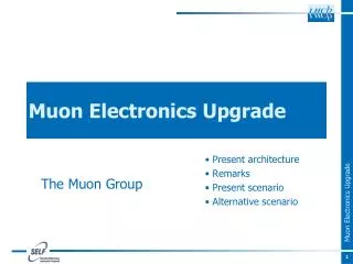
Muon Electronics Upgrade Present architecture Remarks Present scenario Alternative scenario The Muon Group
Present architecture • 5 Stations • L0 links to L0 Muon trigger • Hit information @ 40 MHz • DAQ link to TELL1 • 4 bit TDC information @ max 1 MHz CARIOCA CARIOCA CARIOCA CARIOCA CARIOCA 125k PhysicalChannels DIALOG Programmable Phase Delays Logics, DACs I2C node DIALOG DIALOG 42k LVDS Channels IB SB PDM Low Voltage Intermediate Boards Service Boards PulseDistributionModule Logicalchannels Generation Front-endcontrols ECS nodes 1TTCrx ECS via CANbus 26k LogicalChannels ODE Off Detector Electronic boards L0 ~1000 links NZS @ 40 MHZ L0 () Trigger 1TTCrxfor TFC BX Synchronization Fine Time measurement L0 buffers, I2C node Trigger & DAQ interfaces ODIN L0 yes 24 SYNCs 12 GOL to L0 1 GOL to DAQ DAQ 152 links NZS @ L0 rate TELL1
Present Architecture: Remarks • The 4 bit TDC information is written on disk and is very useful to monitor and fine tune the time alignment of the Muon Stations • This information is sent from ODE boards to the Muon TELL1 via GOL • @ max 1 MHz (~900 ns are needed to read back the complete ODE event) • the events are selected by the L0yes received via the TTCrx from TFC system • However to reconstruct MUONS particles only the 1 bit hit/channel information is used • Currently this information is extracted from the 4bit TDC data (max 1 MHz) • But the same type of information is sent @ 40 MHz from ODE boards to the L0 muon processors with the GOLs • The system is already ready to work at 40 MHz but: • Obsolescence of components could be an issue • No flexibility to match feature run conditions (occupancy, granularity,…) • No zero suppression implementation is possible • TDC data at reduced rate (1 MHz max) • Need to maintain the TFC system and other old ancillary systems
Muon Upgrade in brief • Phase 1: get ready for the 40 MHz readout @ LS2 • The new ODE boards • The new SYNC • The new PDM • Triple-GEM detectors for highly irradiated regions (development only) • New FEE (development only) • Phase 2: new detectors for high-luminosity and new FE electronics prototypes ready @LS2, then construction, to be installed @ LS3 or when needed • Triple-GEM detectors for highly irradiated regions (production) • The new FEE (production)
Phase 1: scenario • New ODE • Design new boards, almost “plug & play” with current ODEs (no need to touch cables from chamber to crates) • Output to TELL40 via GBT: optimized use of bandwidth • Optimized to send both data and TDC info to TELL40 efficiently • No need of legacy TTCRX • L0MU very likely implemented on TELL40, we will have a simple and maintainable system • Control of ODE via GBT will simplify system design and maintenance • New SYNC • Optimized (and simplified) for 40 MHz readout • Contains high-performance TDC • FPGA solution possible but probably marginal a new ASIC much preferred • Remove IB and replace them with nODE • We are seriously considering this option: it is a simple way to reduce overall dead-time in regions where many channels are OR-ed together • No need to touch cabling behind crates (almost everywhere) • need to understand implications with muon trigger
nODE proto-layout • nSYNC daughter boards for better maintenance • 64 input each • 1 or 2 nSYNC chips • Signal synchronization • Phase adjustment • TDC • Zero suppression • Trigger Unit production • 3 or 6 GBT for LLT data and TDC data (simplex) • Separate links for LLT and TDC ? • 1 GBT for ECS (duplex) • 1 GBT-SCA ? • 2 or 3 VTTx • 1 VTRx Trig out Trig out Trig out GBT tirg GBT tirg GBT tirg New SYNC New SYNC New SYNC 64 Input ch 64 Input ch 64 Input ch VTTx VTTx VTTx GBT TDC GBT TDC GBT TDC TDC out TDC out TDC out New SYNC New SYNC New SYNC GBT ECS GBT SCA VTRx
Phase 1: scenario (cont.) • New PDM • Will use GBT (clock and chamber control) • No more need to keep TTCRX compatibility in the whole LHCb • Internally convert control commands to CAN bus to be compatible with existing Service Boards for chamber control • OR use the original backplane to drive a new Service Board that control 1I2C llink without use a intelligent processor mux i2c commands inside GBT data. (avoid ELMB obsolescence in 2020) • New front-end (development only) • Electronics expert strongly push to have a backup solution for the muon front-end in the long run • CoC (Cardiac on chip): will have ASD + DIALOG functionalities, high integration (at least 32 channels/chip, 16 output/chip) • Will allow the increase of detector granularity (if need arise at high luminosity) in a “simple” way: all electronics on chamber, direct readout via fiber to TELL40 • Compatible with new and old detectors to be used as spare for current chambers if needed
Electronics Tentative Timeline (up to LS2) • 2013 • Design of new Muon Detector architecture • Start design of nSYNC • 2014 • Start design of nODE • Some parts of nSYNC submitted • 2015 • First nODE prototypes available (GBT expected in 2015) • Test first nSYNC prototypes • nSYNC design completed, submitted • Start design of nFEE • Work on TELL40 muon part • 2016 • Test nSYNC prototypes • Some partsofnFEEsubmitted • nODEready • nODEtesting • Start work on ECS • TELL40 muon part under test • 2017 • Test first nFEEprototypes • nFEE design completed, submitted • Integration • Finalize ECS work • 2018 • New ECS deployment • Installation and commissioning
Status Information • Front End • Status: • architecture studies ongoing • Technology: • ASIC preferable technology • Data format: • not yet defined • Sync command integration: • not yet defined • Data emulation: • not yet defined • Back End • Data processing • Probably specific but not yet defined • Manpower: • to be defined • Status: • Work not started
Conclusions • The upgrade of the muon detector is converging to a viable solution, allowing to have a modern and more reliable system for the upgrade • Upgrade appears to be cost-effective and can be staged efficiently: • @LS2: readout upgrade • Simple and reliable system • No need to keep compatibility with old standards • Allow much flexibility for future requirements • @LS3: inner regions detector upgrade • Proposed new readout system will allow for a smooth transition to new detector granularities (for R/O and trigger point of view)