
Septic Tank
E N D
Presentation Transcript
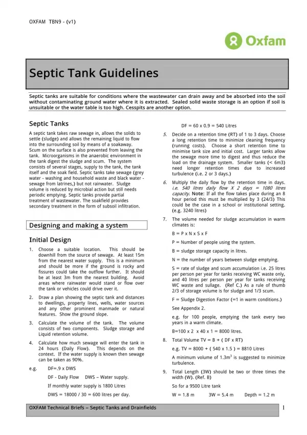
OXFAM TBN9 - (v1) Septic Tank Guidelines Septic tanks are suitable for conditions where the wastewater can drain away and be absorbed into the soil without contaminating ground water where it is extracted. Sealed solid waste storage is an option if soil is unsuitable or the water table is too high. Cesspits are another option. Septic Tanks DF = 60 x 0.9 = 540 Litres A septic tank takes raw sewage in, allows the solids to settle (sludge) and allows the remaining liquid to flow into the surrounding soil by means of a soakaway. Scum on the surface is also prevented from leaving the tank. Microorganisms in the anaerobic environment in the tank digest the sludge and scum. The system consists of several stages, supply to the tank, the tank itself and the soak field. Septic tanks take sewage (grey water - washing and household waste and black water - sewage from latrines,) but not rainwater. Sludge volume is reduced by microbial action but still needs periodic emptying. Septic tanks provide partial treatment of wastewater. The soakfield provides secondary treatment in the form of subsoil infiltration. 5. Decide on a retention time (RT) of 1 to 3 days. Choose a long retention time to minimize cleaning frequency (running costs). Choose a short retention time to minimise tank size and initial cost. Larger tanks allow the sewage more time to digest and thus reduce the load on the drainage system. Smaller tanks (< 6m3) need longer retention times due to increased turbulence (i.e. 2 or 3 days.) 6. Multiply the daily flow by the retention time in days. i.e. 540 litres daily flow X 2 days = 1080 litres capacity. Note: If all the flow takes place during an 8 hour period this must be multiplied by 3 (24/3) This could be the case in a school or institutional setting. (e.g. 3240 litres) 7. The volume needed for sludge accumulation in warm climates is: Designing and making a system B = P x N x S x F Initial Design P = Number of people using the system. 1. Choose a suitable location. This should be downhill from the source of sewage. At least 15m from the nearest water supply. This is a minimum and should be more if the ground is rocky and fissures could take the outflow further. It should be at least 3m from the nearest building. Avoid areas where rainwater would stand or flow over the tank or vehicles could drive over it. B = sludge storage capacity in litres. N = the number of years between sludge emptying. S = rate of sludge and scum accumulation i.e. 25 litres per person per year for tanks receiving WC waste only, and 40 litres per person per year for tanks receiving WC waste and sullage. (Ref C.) As a rule of thumb 2/3 of storage volume is for sludge and 1/3 scum. 2. Draw a plan showing the septic tank and distances to dwellings, property lines, wells, water sources and any other prominent manmade or natural features. Show the ground slope. F = Sludge Digestion Factor (=1 in warm conditions.) See Appendix 2. e.g. for 100 people, emptying the tank every two years in a warm climate. 3. Calculate the volume of the tank. The volume consists of two components. Sludge storage and Liquid retention volume. B=100 x 2 x 40 x 1 = 8000 litres. 8. Total Volume TV = B + ( DF x RT) 4. Calculate how much sewage will enter the tank in 24 hours (Daily Flow). This depends on the context. If the water supply is known then sewage can be taken as 90%. e.g. TV = 8000 + ( 540 x 1.5 ) = 8810 Litres A minimum volume of 1.3m3 is suggested to minimize turbulence. e.g. DF=.9 x DWS 9. Total Length (3W) should be two or three times the width (W). (Ref. B) DF - Daily Flow DWS – Water supply. If monthly water supply is 1800 Litres So for a 9500 Litre tank DWS = 18000 / 30 = 600 litres per day. W = 1.8 m 3W = 5.4 m Depth = 1.2 m 1 OXFAM Technical Briefs – Septic Tanks and Drainfields
OXFAM Septic Tank Guidelines – (draft 1) Sewer Line Fig 1. Septic Tank. 1. The sewer pipe carries the sewage to the septic tank. The line should be at least 15 m away from the source (latrine block, etc.) and down hill from any nearby well or spring, it should be water-tight joints and a uniform slope (minimum 2%). The line should be as straight as possible. 2. The pipe should be hardwearing material (i.e. vitrified clay, concrete, plastic or cast iron.) 3. For latrine blocks individual traps or access points for each latrine should be considered to avoid blockages in the sewer line. Septic Tank Construction Baffle to soakfield inlet scum 40% liquid depth made of non-corrosive, sludge 2W W 1. The walls of the tank can be made of poured, reinforced concrete, stone masonry, brick or concrete blocks. The tank should be made water tight with a 25mm coating of cement plaster, applied in two coats, in order to avoid infiltration around the tank and maintain and anaerobic space. For small tanks the floor need not be reinforced. The space between the walls and the side of the hole need to be filled with gravel or suchlike. The base should be at least 15cm thick. 2. The tank should be divided into two compartments. The first should be twice as big as the second. There is hole in the separating wall which allows liquid to flow through but not scum or sludge. Max velocity through holes is 0.1m/sec to minimise turbulence. Septic Tank Checklist. Your design should: ? Contain wastewater long enough for maximum removal of suspended solids. ? Prevent discharged into the soakfield with the effluent. suspended solids from being ? Provide enough sludge and scum storage space. ? Ensure no blockages are likely. ? Allow adequate ventilation for gases. Fig 2. Basic Tank Dimensions. Groundwater Protection W 2W Permeability Test. Septic tanks are only suitable where soil is permeable enough to allow the soak field to absorb the outflow from the tank, but not so permeable as to cause problems of pollution of the groundwater down stream. The Two Meter Rule. This says that if there is 2 metres of fine sand or loam separating the drainfield and the ground water then virtually all pathogens will be removed. (Ref. A.) This must be true all year round. Water is safe after travelling for ten days. So water can be extracted at least 15m away from a soakaway if the soil is fine. Limestone or fissured rock allows pathogens to travel much further. In unsuitable areas a mound soakaway should be used so that there is at least 2m of soil between the bottom of the soakaways and the water table. These can absorb 5 litres per m2 per day. Water goes into the atmosphere by evapotranspiration by means of plants such as alfalfa. 1.2m min. 1.5m ideal 3W max. W (0.6m) min. 3. Inlet and outlet pipes consist of T pipes. On the outlet this is to avoid scum or solids going into the soakfield. On the inlet this is to reduce turbulence. The base can slope down towards the inlet in a large tank to allow more sludge to be stored. The outlet on a larger tank can be a weir design. 2 OXFAM Technical Briefs Septic Tanks and Drainfields.
OXFAM Septic Tank Guidelines – (draft 1) (see table 1.) 15cm Fig 4. Soakfield trench section. 0.3m Topsoil 15cm outlet Builders paper or straw layer. 45cm Porous or loose jointed pipe Fig 3. Weir design. 1.5 - 2 m Gravel or stones. 0.3-1.0 m 4. If the tank will be below the ground water level at any time the weight of the empty tank should be greater than the weight of water displaced, otherwise the tank may float. 2. The top of the pipe should be laid about 5cm under the building paper/ Straw. 5. Ventilation – The inlet waste water pipe should be ventilated above head height in order to allow the gasses produced in the tank to escape. 3. The bottom of the trench should be above the water table. This may mean a mound has to be made. 6. The roof of the tank can be made of removable sections with lifting handles (easy access) or a solid, reinforced concrete roof with round access holes (min diameter 0.6m) (cannot fall into tank). These provide access to the tank for desludging, checking levels and maintenance. 4. Pipes can be made porous by making them out of concrete without sand, not sealing the joints or, in the case of plastic pipes cutting slots or holes in them (at least 6mm). 5. The slope of the trenches should be 6. Other options are soak pits (small systems), ponds, reed beds or evapotranspiration mounds (high ground water). Soak Field Design 1. A soakfield consists of a series of 15-30m long trenches with open jointed 100mm diameter pipes laid on rocks, broken bricks or gravel. The trenches should be narrow and deep. They should be arranged in series so that each trench overflows into the next one. This means that the trenches will either be fully used or not and avoids a crust forming on the sides. Trenches should be 2m apart. The length of the trench can be calculated using the formula below. Note the base area of the trench rapidly becomes blocked so cannot be included. If the septic tank is not working well the infiltration rate will be lower because the trench will get clogged with solids. Fig 5. Soakfield. Slope From Septic Tank 2m min. L=(N x Q) / 2 x D x I L = Length in metres. N = Number of users. Q = Wastewater flow in litres per person per day. D = Effective depth in meters. I = Infiltration rate in litres per m2 per day. 3 OXFAM Technical Briefs Septic Tanks and Drainfields.
OXFAM Septic Tank Guidelines – (draft 1) Fig 6. Line joining trenches in Soakfield. TD = D + IPD TD = Total Depth D = Depth IPD = Inlet pipe depth e.g. TD = 3.4m +0.6m = 4 m So for this example the ground water depth should be at least 6m. Overflow line Fig 7. Unlined Soakpit. First ½ m Lined Inlet Boulders support pit walls. Table 1. WHO Suggested Infiltration Capacities (Ref. C.) Type of soil Infiltration Capacity. (L / m² per day) (SIR) Coarse / medium sand Fine sand, loamy sand 50 Maintenance 33 1. Organise a maintenance system with schedule (Appendix 1.) and a manual. Sandy loam, loam 25 Porous silty clay / porous silty clay loam 2. Do not overload the system – this will cause clogging of the drainfield. 20 3. Measure sludge and scum levels regularly and empty when needed. Check baffles. Compact silty loam, compact silty clay loam and non-expansive clay 10 4. Do not put strong or hazardous chemicals into the system or use disinfectant. Expansive clay <10 Soak Pit Design. 1. In areas where the ground water level below 4m a soak pit can be used. These can be lined (like a well) or unlined and filled with rocks. 2. The area of the soak pit does not include the base. WA = DF / SIR e.g. WA = 540 L / 50 L/m2 = 10.8 m2 WA =Wall Area DF = Daily Flow SIR = Soil infiltration rate (See table 1). 3. Calculate pit dimensions below inlet pipe. D = WA / π x PD e.g. D = 10.8 / 3.14 x 1 = 3.4m D= depth in meters PD = pit diameter in meters. π= 3.14 4. Add depth of inlet pipe or 0.5m whichever is the highest. 4 OXFAM Technical Briefs Septic Tanks and Drainfields.
OXFAM Septic Tank Guidelines – (draft 1) Latrine Block Vent Distribution Box Soak Field Access Chambers Septic Tank Sewer Line Fig 8. Overall section. Fig 9. Location Plan. Latrine Block 5m Trees Septic Tank Slope 15m 30m Well 30m Note: Plan shows minimum distances. Stream 5 OXFAM Technical Briefs Septic Tanks and Drainfields.
OXFAM Septic Tank Guidelines – (draft 1) Further Information A. Pickford, J. Low Cost Sanitation. IT Publications. 1995. B. Cairncross, S. & Feachem, R. Environmental Health Engineering in the Tropics. John Wiley & Sons 2002. C. A Guide to the Development of on-site Sanitation, WHO, 1992 http://www.who.int/docstore/water_sanitation_health/onsitesan/ch04.htm D. Reed, B. WEDC (2004), Low-Cost Sanitation, Postgraduate Module. Appendix 1. Sample maintenance schedule. Date Action Sludge Level Scum depth. Condition of Person Responsible baffles, etc. Jan 2007 Check Levels March 2007 Empty Tank June 2007 Check Levels Aug 2007 Check Levels Appendix 2. Sludge Digestion Factors ( F ) (Ref. D) Average Air Temp. Desludging period - Years > 20°C all year 10 - 20°C all year < 10°C in winter 1 1.3 1.5 2.5 2 1.0 1.15 1.5 3 1.0 1.0 1.27 6 OXFAM Technical Briefs Septic Tanks and Drainfields.