Chapter 8 Full Depth Concrete Repair
Chapter 8 Full Depth Concrete Repair. From… Maintenance Technical Advisory Guide (MTAG). Learning Objectives. List benefits of full-depth repairs Describe primary design considerations List available types of repair materials Describe the recommended construction procedure

Chapter 8 Full Depth Concrete Repair
E N D
Presentation Transcript
Chapter 8Full Depth Concrete Repair From… Maintenance Technical Advisory Guide (MTAG)
Learning Objectives • List benefits of full-depth repairs • Describe primary design considerations • List available types of repair materials • Describe the recommended construction procedure • List important quality control activities • Describe potential construction and performance problems • Identify troubleshooting solutions
Presentation Outline • Introduction • Design considerations • Construction • Quality control • Troubleshooting
Introduction • Definition Cast-in-place concrete repairs that extend the full-depth of the existing slab • Purpose • Repair localized distress • Preparation for an overlay
Candidate Distresses • Transverse cracking (M, H) • Longitudinal cracking (M, H) • Corner breaks (L, M, H) • Spalling (M, H) • Blowup (L, M, H) • D-cracking (M, H) • Deterioration of existing repairs (M, H)
Benefits • Restored rideability • Restored structural integrity • Prevents further deterioration
Limitations • Does not address structural inadequacy • Not a long-term solution for material-related distresses • Widespread deterioration • Cost considerations
Module 8-1 Design, Materials & Specifications From… Maintenance Technical Advisory Guide (MTAG)
Presentation Outline • Introduction • Design considerations • Construction • Quality control • Troubleshooting
Design Considerations • Selecting repair boundaries • Load transfer design • Selection of repair materials • Curing • Opening to traffic
Selecting Repair BoundariesExtent of Deterioration at Joint Visual deterioration of surface Existing Joint Dowel bar Actual deterioration at bottom of slab
Selecting Repair BoundariesRepair Dimensions • Minimum dimensions • Use lane-width repairs • Length > 1.8 m (6 ft) • Long repairs (>3.7 m [12 ft] long) • Provide reinforcement, or • Provide intermediate doweled joint
Some typical distress conditions noted with L = low M = medium H = high M-H L L M-H L M M d d d d d d No repair required Replace entire slab-outer lane d = 1.8 m (6 ft) minimum Selecting Repair BoundariesRepair Recommendations (JPCP)
L L L H L L L L L L L L M L L M L L H L M-H L L H M Some typical distress conditions noted with L = low M = medium H = high d d d d Replace entire slab-outer lane d d d = 1.8 m (6 ft) minimum Selecting Repair BoundariesRepair Recommendations (JRCP) No repair required
Selecting Repair BoundariesMulti-Lane Considerations • Adjacent lanes can be repaired independently • Matching joints is not essential • Avoid small offsets • If blowups in adjacent lane • Delay until cooler weather • Cut pressure relief joints
Load Transfer DesignRecommendations Traffic Direction Mid-depth slab Smooth dowels or deformed rebars Smooth dowels 38 mm (1.5 in) dia. 0.6 m (2 ft) 3.7 m (12 ft) 0.3 m (1 ft) typical 1.8 m (6 ft) minimum
Repair MaterialsRecommendations • PCC mixes • Rapid set cement (RSC) • Regulated set portland cement (RSPC) • Proprietary materials
Curing • Curing compound • Insulation blankets • HIPERPAV software
Opening to Traffic • Opening criteria • Minimum strength • Minimum time • Typical strength • 13.8 MPa (2,000 psi) compressive • 2.1 MPa (300 psi) center-point • 1.7 MPa (250 psi) third-point
Typical Item Codes http://i80.dot.ca.gov/hq/esc/oe/awards/#item_code
Module 8-2 Construction and Inspection From… Maintenance Technical Advisory Guide (MTAG)
Presentation Outline • Introduction • Design considerations • Construction • Quality control • Troubleshooting
Construction Procedure • Concrete sawing • Concrete removal • Repair area preparation • Load transfer provision • Material placement • Curing • Joint sealing
Concrete SawingConsiderations • Full-depth, diamond-bladed sawing • Pressure relief cuts on hot days • Limit traffic loading on sawed pavement to avoid pumping • If asphalt shoulder present, remove 150 mm (6 in) for form space
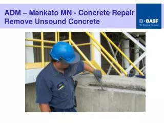
Concrete RemovalBreakup and Cleanout Method • Advantages • Efficient breakup of concrete • Rapid removal of concrete onto trucks • Disadvantages • Greatly disturbs subbase • Potential to damage slab
Concrete RemovalLiftout Method • Advantages • Does not disturb subbase • More rapid material removal • Disadvantages • Disposal of large concrete pieces • Process requires lifting pins and heavy lifting equipment
Load Transfer ProvisionDrilling Recommendations • Dowel holes drilled on 305 mm (12 in) centers at mid-depth • Dowel holes drilled slightly larger than dowel diameter • Smooth steel dowel bars or deformed tie bars can be used
Load Transfer ProvisionDowel-Bar Placement • Blow debris and dust from holes • Place grout or epoxy in holes • Insert dowel into hole with slight twisting motion • Install grout retention disks • Grease protruding dowel ends
Load Transfer ProvisionDowel-Bar Placement Existing slab Grout-retention disk (optional) Anchoring material Hole dia. = d+a Repair area d = dowel diameter a = 2 mm (1/8 in) for epoxy Subbase a = 6 mm (1/4 in) for cement grout Subgrade Soil
Material Placement • Consolidation and level finish are critical • Vibrate along edges of repair • Avoid addition of extra water • Texture surface to match existing pavement
Joint Sealing • Saw and seal as soon as possible after placement • Follow the procedures described in Module 3-1