Download
1 / 16
160 likes | 330 Vues
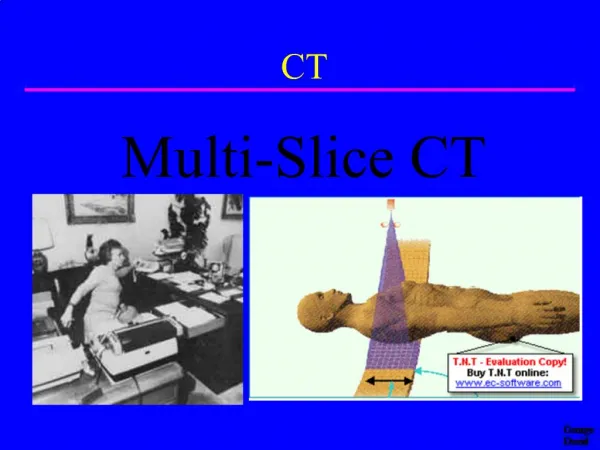
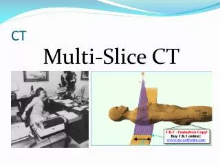
RAD 354 Chapt . 23 Multi-slice CT. In short – CT is a thin band (fan) of radiation directed toward the pt. and the remnant radiation emitted from the pt. is measured by a receptor and the response transmitted to a computer for reconstruction of the image(s). “Slip rings”.

E N D
RAD 354 Chapt. 23 Multi-slice CT • In short – CT is a thin band (fan) of radiation directed toward the pt. and the remnant radiation emitted from the pt. is measured by a receptor and the response transmitted to a computer for reconstruction of the image(s)
Dates/Activities to Remember • 1970 – Sir Godfrey Hounsfield,Ph.D.., demonstrated the technique of CT scanning – “EMI” head unit
Dates/Activities Con’t. • 1982 Dr. Hounsfield and Dr. Alan Cormack share the Nobel Peace Prize in physics • CT Generations and important items: • 1st – translate-rotate; “pencil beam” - one full rotation for 1 image; head only; 5 min. per image! • 2nd – translate-rotate, but with a “fan” beam; produced INCREASED INTENSITY at the edge of the beam – “bow-tie” filter used to remedy this; 30 sec. image time
Generations con’t. • 3rd – used ARRAY of DETECTORS – produced “ring artifacts” • 4th rotate – stationary, fan beam, detector array; short image time and NO re-con time! • 5th is NOW here! “Spiral/slip ring” (It is slip ring technology that has enabled this latest generation!)
Major Components of CT • Gantry – tube-receptor array, collimators (pre-pt. and pre-detector), generator, pt. couch • Computer – microprocessor – recon time was a BIG issue until recently • Operating console – usually two monitors – one for RIS/HIS and the second for the imaging portion (often times a “remote” monitor is set up at the radiologist’s desk – can really be a hassle)
Current – 5th Generation Terms • Spiral • Helical • 16/32/64 slice • Slip Rings CT
Interpolation/Extrapolation • Interpolation – information ALONG the axis WITHIN established values • Extrapolation – information OUTSIDE axis values established, BUT an ESTIMATED value based upon previously measured parameters IF they continue
“Spiral” Terms • Pitch – relationship between couch movement and x-ray beam collimation (pitch ratio) • Increasing pitch ratio enables much MORE of the pt. to be imaged in ONE BREATH HOLD! Breath holds = misrepresentation of the images. • Slip ring technology made “spiral CT” possible • Three slip rings in the gantry (usually) • One for hi voltage power to the tube and hi voltage generator • Low voltage power to the rotating gantry portion • Transfer of digital data from gantry receptors to the computer
Multi Slice CT • Multi detector arrays • Two at once with one beam = two slices per 360 degrees • With “spiral” enables two detectors to produce 16 slices • Envision a person on the table/couch in a screw/nut fashion going through the gantry
Maximum Intensity Projection (MIP) • Pre selecting pixel levels to be viewed AFTER obtaining a “rubic’s cube of information” • Then only exhibit those at the PRE-DETERMINED value – like an MRA or CTA
Spiral Advantages of Conventional CT • Motion blur is reduced – fewer artifacts • Lowered imaging time (fewer breath holds required = less motion and less mis-representation) • Larger volumes can be imaged with LESS part overlap artifacts