FPLC
FPLC. All you need to know – in the available time!. FPLC. Fast Performance Liquid Chromatography- Liquid chromatography is a term which refers to all chromatographic methods in which the mobile phase is liquid. The stationary phase may be a liquid or a solid, in the form of a matrix


FPLC
E N D
Presentation Transcript
FPLC All you need to know – in the available time!
FPLC • Fast Performance Liquid Chromatography- Liquid chromatography is a term which refers to all chromatographic methods in which the mobile phase is liquid. • The stationary phase may be a liquid or a solid, in the form of a matrix • A type of liquid chromatography where the solvent velocity is controlled by pumps. The pumps control the constant flow rate of the solvents
FPLC • The solvents are accessed through tubing from an outside reservoir. • The flow rate of the solvent is set through computer input and controlled by pumps. • There are various columns used in liquid chromatography depending on the type of separation preferred. Each column contains a small diameter packing material. The column is a large (mm id) tube containing small (u) particles (gel beads) known as stationary phase.
FPLC • The chromatographic bed is composed by the gel beads alone when they are inside the column. • The sample is introduced into the injector and then carried into the column by the flowing solvent. • Once in the column, the sample mixture separates as a result of different components adhering to or diffusing into the gel.
FPLC • As the solvents is forced into the chromatographic bed by the flow rate, the sample separates into various zones of sample components. These zones are referred to as bands. • Biomolecules have various characteristics such as molecular weight, electric charge, and hydrophobicity. • As so, purification of the object is usually achieved by using a combination of chromatographic methods
Answer- everything!!!!!!! • Only difference with FPLC and HPLC is pressure • HPLC allows for smaller column matrix due to the increased pressure. • Remember the The Van Deemter Equation? • Allows solute to equilibrate between mobile and stationary phase faster • HPLC is a better choice for analytical analysis.
Applications • Ion Exchange chromatography • Separates compounds based on their net charges. Negatively or positively charged functional groups are covalently bound to a solid support, yielding either a cation or anion exchanger, respectively. • Hydroxyapatitechromatography • (Ca5(PO4)3(OH)2 is a form of calcium phosphate that can be used for the separation and purification of proteins, enzymes, nucleic acids, viruses, and other macromolecules.
Applications • Affinity chromatography • A ligand is covalently bound to a solid support that is packed into a chromatography column. • A mixture of components is then applied to the column. The unbound contaminants, which have no affinity for the ligand, are washed through the column, leaving the desired component (protein, peptide, DNA fragment, etc.) bound to the support. • Elution is accomplished by changing the pH and/or salt concentration, or by applying organic solvents or a molecule that competes for the bound ligand.
Applications • Reverse-Flow Chromatography for Affinity Purifications • Especially useful when purifying antibodies using Protein A or other affinity columns. • The protein is bound at the top of the column and nonbinding material is washed out. • Flow to the column is then reversed and the bound proteins elute from the top of the column in very concentrated form, which helps prevent denaturation.
Applications • Size exclusion chromatography (SEC) • Also known as gel filtration chromatography • The gel medium consists of spherical beads containing pores of a specific size distribution. Separation occurs when molecules of different sizes are either included or excluded from the pores within the gel support. • Small molecules diffuse into the gel pores and their flow through the column is retarded, while large molecules do not enter the pores and are rapidly eluted in the column's void volume.
Applications • Size exclusion chromatography (SEC) • Consequently, molecules separate based on their size as they pass through the column and are eluted in order of decreasing molecular weight. • Common applications include fractionation and molecular weight determination of proteins, nucleic acid separation, plasmid purification, and polysaccharide fractionation.
Applications • Size exclusion chromatography (SEC) • Resolution depends on particle size, pore size, flow rate, column length and diameter, and sample volume. • Generally, the highest resolution is obtained with low flow rates (2–10 cm/hr), long, narrow columns, small-particle-size gels, small sample volumes (1–5% of the total bed volume), and a sample viscosity that is the same as the eluent.
Applications • Hydrophobic interaction chromatography (HIC) • Separates molecules based on their hydrophobicity. • Sample molecules containing hydrophobic and hydrophilic regions are applied to an HIC column in a high-salt buffer. • The salt in the buffer reduces the solvation of sample solutes. As solvation decreases, hydrophobic regions that become exposed are adsorbed by the medium. • The more hydrophobic the molecule, the less salt needed to promote binding. • Usually a decreasing salt gradient is used to elute samples from the column in order of increasing hydrophobicity.
Applications • Immobilized metal ion affinity chromatography (IMAC) • Most widely used – nickel: also zinc and cobalt • Nickel binds molecules rich in electrons – such as histidine (from the His-tag fame!) • Consists of string of 6-10 histidine residues. Serve as a metal binding site • IMAC uses the affinity of histidine’s imidazole side chains for metal ions
Applications • Immobilized metal ion affinity chromatography (IMAC) • The His-tag allows the protein to bind to the column beads • Note – proteins with a naturally high histidine residues will also bind • The elution buffer (containing imidazole) is then added to the column • Competes with nickel for bound ligands and collection in fractions
Applications • Immobilized metal ion affinity chromatography (IMAC) • THIS IS WHAT YOU WILL BE DOING!!!!!!!!!!!
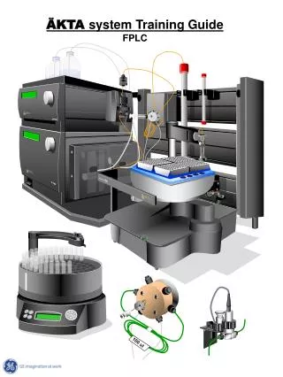
Bio-Rad Biologic Duoflow system • 1. UV Detector With Conductivity Monitor • 2. SV5-4 select valve4. AVR9-8 switching valves7. F40 workstation • 8. BioFrac fraction collector • 9. AVR 7-3 sample inject valve
UV Detector With Conductivity Monitor • Standard 254 and 280 nm filters • Replaceable mercury lamp • 214 nm expansion kit with zinc lamp • 365, 405, 436, and 546 nm expansion filters for the mercury lamp • Analytical 5 mm flow all UV absorbance range from 0.0001 to 2.0 OD • Conductivity detection range from 1 to 500 mS/cm
Conductivity • NaCl is an electrolyte • Becomes sodium ions (Na+) and chlorine ions (Cl-), each of which is a corpuscle that conducts electricity. • IONS – from the Greek word meaning wonderer • This means that the more Na+ and Cl- contained in water the more electricity is carried, and the higher the conductivity
Bio-Rad Biologic Duoflow system • 1. UV Detector With Conductivity Monitor • 2. SV5-4 select valve4. AVR9-8 switching valves7. F10 workstation • 8. BioFrac fraction collector • 9. AVR 7-3 sample inject valve
SV5-4 select valve • The SV5-4 valve is a low pressure, 5-port, 4-position valve used for automatic buffer selection and sample loading. • The SV5-4 valve may be used for: • Buffer and/or sample selection when placed before the Workstation pumps. • enables access to four separate solutions • Purging or rinsing all tubing lines for cleaning purposes
Bio-Rad Biologic Duoflow system • 1. UV Detector With Conductivity Monitor • 2. SV5-4 select valve4. AVR9-8 switching valves7. F10 workstation • 8. BioFrac fraction collector • 9. AVR 7-3 sample inject valve
F10 workstation • The BioLogic DuoFlow workstation has a F10 pump, • Max flow rate of 10 ml/min • Pressure: 3,500 psi (233 bar, 23 MPa).
Bio-Rad Biologic Duoflow system • 1. UV Detector With Conductivity Monitor • 2. SV5-4 select valve4. AVR9-8 switching valves7. F10 workstation • 8. BioFrac fraction collector • 9. AVR 7-3 sample inject valve
AVR 7-3 sample inject valve • The Load position is for filling a loop with sample or for running buffer through a column • The Inject position is for injecting contents of the sample loop onto a column; • The Purge position is for priming the DuoFlow workstation gradient pump and purging lines to waste without removing the column from the system.
The Mixer • The mixer ensures that the buffers used are in the correct proportion relative to each other during the course of the FPLC run • Comes into its own as the gradient increases!
Bio-Rad Biologic Duoflow system • 1 QuadTec UV/Vis detector • Monitor off-peak wavelengths such as 245 nm (instead of 280 nm, where buffer components like Triton X-100 absorb strongly). • Can simultaneously monitor at 224 nm for greater protein sensitivity without background interference.
MAXIMIZER • 5) The Maximizer enables buffer blending applications, doubles pump flow rates, and doubles valving capacity to 6 low pressure valves and 6 high pressure valves. • Proportioning valves on the Maximizer blend water, salt, and the conjugate acid and base of a buffer to obtain a solution with a user-defined pH and salt concentration.
MAXIMIZER • For example, after the user selects the desired pH for each separation, the software determines the required acid/base ratio and during the run compensates for changes in ionic strength and temperature. • This provides tremendous convenience by enabling multiple unattended runs, each at a different buffer pH and salt concentration.
Before you load your sample • Degassing: • One major problem with pressurizing chromatography systems using liquid solvents is that pressure reductions can cause dissolved gases to come out of solution. • The two locations where this occurs are: • the suction side of the pump (which is not self-priming, consequently a gas bubble can sit in the pump and flow is reduced ). • the column outlet (where the bubbles then pass through the detector causing spurious signals).
Before you load your sample • Degassing: • The problem is usually restricted to solvents that have relatively high gas solubilities - usually involving an aqueous component, especially if a gradient is involved where the water/organic solvent ratio is changing. • As water usually has a higher dissolved gas content, then a gradient programme may cause the gases to come out of solution as the mobile phase components mix.
Before you load your sample • Degassing: • There are two traditional strategies used to remove problem dissolved gases from chromatographic eluants. Often they are used in combination to lower the dissolved gases. • Subject the solvent to vacuum for 5-10 mins. to remove the gases. • Subject the solvent to ultrasonics for 10-15 mins. to remove the gases. • Note that most aqueous-based solvents usually have to be degassed every 24 hours. Also remember that solubility of gases increases as temperature decreases, so ensure eluants are at instrument temperature prior to degassing.
Degassing • The Backpressure Regulatorhelps eliminate bubble information within the detector. • As a solution is pumped through a column, the column exerts a backpressure that serves to keep any air bubbles in solution. • Solution exiting the column returns to atmospheric pressure and air bubbles may form.
Degassing • As the bubbles pass through, or lodge in the detector flow cell they may cause artifacts on the baseline chromatogram that appear as spikes. • This “outgassing” may be minimized by thoroughly degassing buffers and by placing a backpressure regulator after the Conductivity monitor. • The backpressure from the regulator helps to keep the bubbles in solution
Degassing • The 40 psi backpressure regulator is used with flow rates below 10 ml/min. • Plumb the backpressure regulator following the direction of the arrow. • When using low pressure columns such as an Econo-Pac® cartridge, plumb the 40 psi backpressure regulator between the Workstation pump outlet and the mixer. This aids in seating the check valves, preventing permanent damage to the cartridge or column
Prime the FPLC pumps • In the manual mode, prime the FPLC pumps and wash the buffers through the hoses. • Do this in the PURGE mode for the injection solenoid
Prime the FPLC pumps • Be careful not to let the last person’s buffer contaminate yours. You will want to flush the sample loop to remove water or old samples. • Look at the routing displayed on the sticker on the solenoid and make sure you know what is going where.
AVR 7-3 sample inject valve • AVR7-3 in Load Position (Figure A) • The column may be equilibrated or eluted. • Sample is loaded into the loop. If the loop is overfilled, the sample runs to waste. • Never remove the syringe before the sample is injected onto the column
AVR 7-3 sample inject valve • AVR7-3 in Inject Position (Figure B) • The sample is injected onto the column
AVR 7-3 sample inject valve • AVR7-3 in Purge Position (Figure C) • Flow from the gradient pump goes directly to waste, bypassing the column.
Basic AVR7-3 Sample Injection Valve Operation using Load, Inject, and Purge Positions • Load position is for filling a loop with sample or for running buffer through a column. • Inject position is for injecting contents of the sample loop onto a column. • Purge position is for priming the Duo-Flow workstation gradient pump and purging lines to waste without removing the column from the system.
The bloody machine looks like a Borg! • Yes, The FPLC does look like a Borg!!!! However, do not panic! Remember to look over All of the instructions, follow the lines and you will see how it all works!
Computer control Flow Rate: The flow rate for washing and eluting can be around 1.0 – 2.0 ml/min. Experiment with elution flow rates. Equilibration with the equilibration buffer can be performed at the same flow rate Fractions: Typically, I will collect 0.5-1.5 ml fractions for a 1 ml column and a 1-2.5 ml fractions for a 2-5 ml column. Collect when you want, the whole thing or just specific fractions.