Download
1 / 6
70 likes | 206 Vues
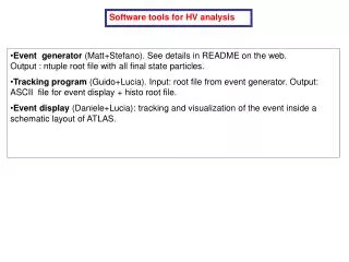
Software tools for HV analysis. Event generator (Matt+Stefano). See details in README on the web. Output : ntuple root file with all final state particles.

E N D
Software tools for HV analysis • Event generator (Matt+Stefano). See details in README on the web. Output : ntuple root file with all final state particles. • Tracking program (Guido+Lucia). Input: root file from event generator. Output: ASCII file for event display + histo root file. • Event display (Daniele+Lucia): tracking and visualization of the event inside a schematic layout of ATLAS.
Tracking program(root macro). Input: root file from event generator. • Functionalities: • organize the event in vertex-track structures(max 30 vertices,max 200 tracks/vertex) • typedef struct vertex{ • float point[3]; (vx coordinates) • int ntx; (n of tracks of this vertex) • Trk track[200]; • } Vx; • typedef struct track{ • Vect p; ( momentum vector) • float point[3]; (vx coordinates) • float charge; • float mass; • int mcode; (mass code for tracking: 0 neutrinos 1:gamma,electrons 2:hadrons 3: muons) • int stop; (track end point code.See volume flag in table1) • } Trk;
prepare the ascii file for the display program (organized in vertces and particles produced at each vertex). • trace inside the detector: all particles are traced inside a simplified version of ATLAS (detectors are schematized as cylindroids with r min ,r max and zmin,zmax; see Fig.1).Tracing is stopped according to the mass code; mc=1 stop at the entrance or inside the em calo or inside the hadron calo mc=2 stop at the entrance or inside the hadronic calo mc=3 trace up to the last muon plane. The stop volume is recorded in the stop code of the track. Hadronic tracks from vertices produced in the last 25 cm of the hadronic calo are traced inside the muon spectrometer. • hit generation: the stop of each track produces a hit in the proper hit list (emhit,hdhit muhit). Tracing inside the muon spectrometer : a hit is produced each time an MDT plane is crossed. For the BML chambers two hits are produced representing the two RPC trigger planes).The hit structure is as follow: • typedef struct hit{ • float xyz[3]; • float dircos[3]; • float e; • float et; • float eta; • float phi; • int ifla; (volume flag: see table 1) • int ntrk; (sequential number of the particle in this vertex) • } Hit;
First level muon trigger simulation: using the hits of the previous step a simplified version of the muon trigger algorithm has been implemented. Only the barrel part is activated due to the difficulty in reproducing the magnetic field in the transition region. • First level calo trigger: in preparation(Carlo). • Missing et, sum et and event by event calorimeter lego plots are also available.
ATLAS geometry description Table 1
(15,2) (5,3) (4,3) (0,0) (15,2) (3,0) (3,0) (4,0) (2,1) Fig. 1