Download
1 / 12
120 likes | 136 Vues
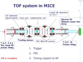
This system utilizes MICE Liquid H2 absorbers or LiH to eliminate muons that decay and tracks particles using TOF detectors. It features precise timing, pion/muon identification, and compensation coils for accurate measurements. The system also includes solenoids, spectrometers, and RF cavities.

E N D
TOF system in MICE Liquid H2 absorbers or LiH ? SC Solenoids; Spectrometer, focus pair, compensation coil Electron ID Eliminate muons that decay Tracking devices 201 MHz RFcavities T.O.F. II Precise timing T.O.F. 0 & I Pion /muon ID precise timing • Trigger • PID • Timing respect to RF MB TOF 0, I-II positions
Tof detector structure • Conventional fast scintillator bars, read by PMTs at both ends, arranged in planes (Y or X/Y for better performances) for 3 stations: T0,T1,T2 • Aimed performance 70 ps • Bars are staggered and overlapped at the edges (for cross calibrations with incoming particles) • Calibration: beam particles impinging on overlaps + dedicated fast laser system (a la Harp) MB
A layout of the Laser calibration system (Harp system) Laser Nd-YAG with passive Q-switch (dye), active/passive mode locking and 10 Hz repetition rate IR emission converted to a second harmonic (l=532 nm) by a KD*P SHG crystal Pulse: width 60 ps energy 6 mJ • Beam splitter: • To ultra-fast (30 ps rise/fall) InGaAs MSM photodiode = START • To detector slabs through custom-made optical fibre system = STOP Foreseen mod: introduction of an optical switch to deliver signal to single channel MB
Main experimental problems: • T0: high incoming particle rate (at least some MHz). Solution: R4998 PMTs with modified divider circuit (it can sustain up to 1.6 MHz, but small tolerance to B fiels) • T1,T2: high magnetic fields. Solution: global iron shield+ fine-mesh PMTs (R7761, R5505) • Tests under way: laboratory rate tests for PMTs, fine-mesh PMTs tests in B field MB
PMT rate studies R4998 with modified divider circuit: booster for last dynodes Lab rate tests to be done with: • Hamamatsu PLP-10 fast laser (35 FWHM, 1Hz-1MHz rate, 415 nm) • Fiber launching system into IR multimode fiber (Ceram OPTEC UV 50/100, measured spread 15 ps/m) • PMT signal read by QVT (35 ps resolution) Nominal: up to 1.5 MHz MB
Preliminary rate effects tests • Please insert here .prn file available MB
PMTs for TOF1,TOF2: problems with high magnetic field Fine-mesh PMTs may not be enough • Figure shows |B| from the cooling and measurement solenoids. • The phototubes are placed in a place with high field. • B may be bigger than 1 T -> problems TOF II ? MB
First step: global soft iron shield for downstream detector (GG) MB
Solution from Ghislain: single iron slab 15-cm thick with a central hole of 40 cm-diameter r (cm) B is greatly reduced well below 1 T No problem for PMTs Z (cm) O Field map covers the domain 0 < z < 135 cm and 0 < r < 100 cm (dashed rectangle) MB
Second step: systematic fine-mesh PMTs test in B-field (up to 1.2T) PMT under test Light source: Laser diode Hitachi DL3038-011 (635nm) pulsed by a pulser (Lecroy 9210, risetime 300 ps) FWHM laser pulse 300 ps. Injection in a short optical fiber to a prism, giving light to the PMT Output PMT signal to a Silena QVT MB
Fine-mesh phototube Properties Under test MB
Test magnet at LASA. First typical results. • Timing measurements • Gain measurements • As a function of B, • More measurements under way MB