Download
1 / 35
350 likes | 471 Vues
United Arab Emirates University College of Engineering Mechanical Department . Design a ship base using adhesively bonded hollow steel members to Reinforce Aluminum Plates. Mohammed Jassem Al Hosani 200301436 Osama Ebrahim Al Zaabi 200305397

E N D
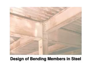
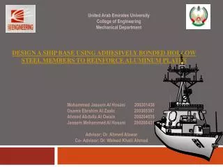
United Arab Emirates University College of Engineering Mechanical Department Design a ship base using adhesively bonded hollow steel members to Reinforce Aluminum Plates Mohammed Jassem Al Hosani 200301436 Osama Ebrahim Al Zaabi 200305397 Ahmed Abdulla Al Owain 200204035 Jassem Mohammed Al Hosani 200200431 Advisor; Dr. Ahmed Alawar Co- Advisor; Dr. WaleedKhalil Ahmed
Contents • Introduction • Methods & Techniques • Testing • Lower deck’s calculations • Results & Discussions • Testing results • Lower deck results • Finite element • Conclusions & Recommendations
Introduction • project our aim is to find out the efficiency of reinforcing an aluminum plate by using adhesively bonded hollow steel sections for strengthening or rehabilitation of marine applications and to investigate the performance characteristics and failure mechanisms in comparison with similar welded fabricated sections. • This project will be prove that constructions of steel structures for the marine industry to be practicable using modern structural adhesives. These adhesively bonded structures are efficient form of paneling.
Introduction • This project will include investigating the use of hollow steel and aluminum reinforced plates as materials. The metallic hollow members made of steel were usually welded to the reinforced plates. As a part of this investigation, these hollow members will be adhered to the plates rather than welded and then will be compared to the welding results. In addition, an experimental optimization process will be done to determine the required area for the adhesive interface to sustain the load as per the design. Finite element software might be needed to analyze and compare the date.
Introduction • The objective of this project is to find out the efficiency of reinforcing aluminum plate by using adhesively bonded hollow sections to compare with similar welded fabricated sections. Welding is a fabrication process that joins materials, usually metals or thermoplastics, by causing coalescence. This type of operation is used widely in ship manufacturing. Adhesive method is a new technology that used in the ship manufacturing so that we use a special type of resin to manufacture the lower deck of the ship. The group will handle a complete design problem that involves; • Design calculations • Experimental work • Data analysis in addition to finite element modeling
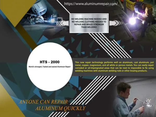
Methods & Techniques • Testing • Bonding the specimens Epoxy and Hardener
Methods & Techniques • Testing • Bonding the specimens Mixing the epoxy and hardener until homogeneously occurs
Methods & Techniques • Testing • Bonding the specimens Cleaner
Methods & Techniques • Testing • Bonding the specimens Bond the specimens
Methods & Techniques • Testing • Experiment In order to run the testing, we follow these steps; 1-We did the testing using 9 specimens. The following tables represent combinations between the specimens by using the welding and bonding and the dimensions of each piece.
Methods & Techniques • Testing • Experiment 2-Use block bearing to prevent making local buckling 3-Use strain indicator to indicate the strain.
Methods & Techniques • Testing • Experiment 4-Use strain gage at the center of the rips and connected it to the strain indicator. 5-Start the testing. 6-Stop the Testing after 15 min loading.
Methods & Techniques Lower deck’s calculations • Mass applied= 500 kg/m2 with a uniform load • Transverse beams are hollow steel beams; • General structural steel • Longitudinal beams are steel I beams; • General structural steel • Aluminum plate with thickness of 6mm; • AL-5083H112 • The distance between transverse beams is 30 cm
Methods & Techniques Lower deck’s calculations • Calculate the number of rips needed; • Total force applied on each rip; • Maximum bending moment;
Methods & Techniques Lower deck’s calculations • Modulus of elasticity for the composite; • Centroid of the composite;
Methods & Techniques Lower deck’s calculations • The moment of inertia calculated as follow;
Methods & Techniques Lower deck’s calculations • Finally, we calculate the allowable stress and the deflection of the transverse beams; the equation of section modulus is;
Results & Discussions • Testing results • Experimental Results The steel/steel welded and the maximum deflection which it was 1.5 mm at load 4000N within the elastic rang.
Results & Discussions • Testing results • Experimental Results The steel/steel adhered and the maximum deflection which it is 1.5 mm at load 6000N.
Results & Discussions • Testing results • Experimental Results Thesteel/aluminum adhered and the maximum deflection which it was 1.5 mm at load 7000N
Results & Discussions • Testing results • Finite Element Finite element results
Results & Discussions • Testing results • Finite Element Average lap shear strength for typical metal to metal joints
Results & Discussions • Testing results • Finite Element The distribution of stresses on the welded steel
Results & Discussions • Testing results • Lower deck results Properties for the plate and transverse beam/rip
Results & Discussions • Testing results • Lower deck results Number of rip and bending moment maximum deflection for transverse beams/rips
Results & Discussions • Testing results • Lower deck results Centroid for the transverse beam
Results & Discussions • Testing results • Lower deck results Moment of inertia for the composite
Results & Discussions • Testing results • Lower deck results Allowable stress and the maximum deflection for transverse beams/rips
Results & Discussions • Testing results • Lower deck results Section modulus for longitudinal I beam
Results & Discussions • Testing results • Lower deck results Allowable stress and the maximum deflection for longitudinal I beams
Results & Discussions • Testing results • Lower deck results Allowable stress and the maximum deflection for longitudinal I beams
Results & Discussions • Testing results • Finite Element Boundary conditions and distributed load on the lower deck
Results & Discussions • Testing results • Finite Element Deflection of the lower deck
Results & Discussions • Testing results • Finite Element Strain on the lower deck
Results & Discussions • Testing results • Finite Element Strain on adhesive layer