Download
1 / 27
540 likes | 1.49k Vues
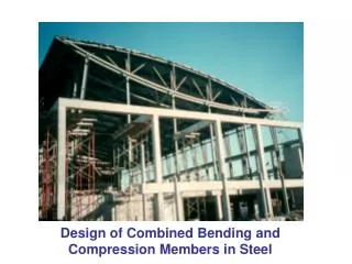
Design of Steel Flexural Members. Design for : Economy – choose lightest beam that can carry the load Serviceability – May need deeper beam to prevent serviceability problems such as deflection or vibrations. Design of Steel Flexural Members. Bending about strong axis (x-axis):

E N D
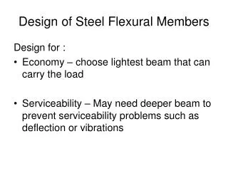
Design of Steel Flexural Members Design for : • Economy – choose lightest beam that can carry the load • Serviceability – May need deeper beam to prevent serviceability problems such as deflection or vibrations
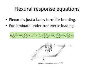
Design of Steel Flexural Members • Bending about strong axis (x-axis): • Bending about weak axis w X X w Y Y
Stress and Strain in the Cross-section Strain Stress N.A. N.A. ε=εy ε=εy small ε small ε plastic ε plastic ε E = F/ε E ≠ F/ε N.A. small F Fy Fy Fy
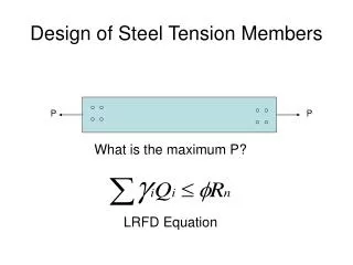
LRFD Equation Load Effect ≤ Factored Resistance
Part 5 – Design of Flexural Members • Beam Tables – Table 5-3, p. 5-42 – 5-48 • Beam Charts – Table 5-5, p. 5-71 – 5-102 • Beam Diagrams – Table 5-17, p. 5-162 – 5-177
Flexural Design Example p. 27 notes You are to select the lightest A992 steel beam that can carry a live load of 1.9 k/ft and a dead load of 1.4 k/ft for a span of 33 feet. Assume first continuous lateral support, and then lateral support 10 ft from each end only.
Flexural Design Example p. 27 notes Select an A36 channel to carry a 500 lb/ft live load and a 300 lb/ft dead load for a simply supported span of 15 ft. Lateral support will be continuous for both flanges.
Deflections • Serviceability (not strength) – Chapter L • Calculated for service live load only • KBC: • ∆max = L/360 floor members • ∆max = L/240 roof members where ∆max = maximum deflection L = span length
Deflections p.5-11 LRFD Can also be written
Beam Shear Maximum moment: Also an internal shear: w w M V R
Shear Strength of Beams p. 16.1-35 LRFD (with no holes in web) if, where, Fyw = yield strength web = Fy for steel shapes Aw = area of web = d x tw p. 16.1 – 67 At connection where holes are in web: true for steel shapes
Floor Systems for Steel Frame Structures Typical floor systems consist of steel decking filled with concrete Figures of steel decking p. 16.1- 223 (Commentary to chapter I)
Design Example with Floor System p. 33 notes Design the floor system for an office building using the KBC minimum distributed live load for corridors (to allow flexibility of office space). The depth of the floor beams is limited to 24.5” to allow space for mechanical systems. Use EC366 steel decking and lightweight concrete without shoring.
30’ 24.5” 45’ 30’ 30’ 30’
Composite Construction • Detail of shear connectors
Composite Construction PNA in steel PNA in concrete b b a Ycon Ycon C = Ccon+Cst Tst C=T b b a C con Ycon Tst
Composite Construction Ccon = 0.85f’cba T = FyAs C and T can not exceed force carried by studs, ∑Qn ∑Qn =0.85 f’cba Depth of compression block
Composite Construction p.5-33 • Y1 – Distance from PNA to beam top flange • Y2 – Distance from concrete flange force to beam top flange • b – effective width of concrete slab flange • a – effective concrete flange thickness