Download
1 / 13
170 likes | 627 Vues
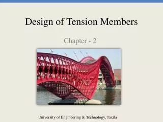
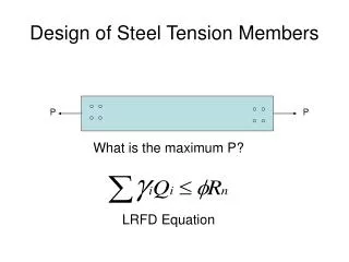
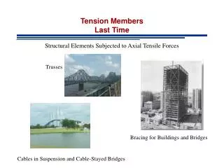
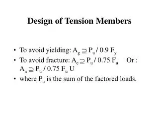
Design of Tension Members. To avoid yielding: A g P u / 0.9 F y To avoid fracture: A e P u / 0.75 F u Or : A n P u / 0.75 F u U where P u is the sum of the factored loads. Design of Tension Members.

E N D
Design of Tension Members • To avoid yielding: Ag Pu / 0.9 Fy • To avoid fracture: Ae Pu / 0.75 Fu Or : An Pu / 0.75 Fu U • where Pu is the sum of the factored loads.
Design of Tension Members • If the axial load in a slender tension member is removed and small transverse loads are applied, undesirable vibrations or deflections may occur. Thus AISC recommends: • r L/300 ( not for cables or rods) • where r is the minimum radius of gyration of the cross section and L is the length of the member.
Threaded Rods and Cables • When slenderness is not a consideration, circular rods and cables are often used (hangers, suspended bridges). • Rods are solid and cables are made from individual strands wound together. • Threading the end of a rod reduces the cross sectional area (upset end prevents such reduction, but is expensive).
Threaded Rods and Cables • t Pn = 0.75 (0.75 Ab Fu) • Ab = nominal (unthreaded) area • It is common to use a min diameter of 5/8 in. for rods.
Threaded Rods and Cables • A strand consists of individual wires wound helically around a centrl core. • A wire rope is made of several strands laid helically around a core.
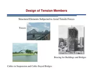
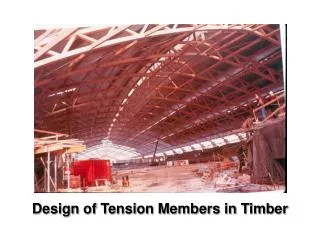
Tension Members in Roof Truss • Trusses are used where the cost and weight of a beam could be prohibitive (long spans). • A truss may be thought of as a deep beam with much of the web removed. • Tension members in roof trusses include some truss members and sag rods.
Sag Rods • Sag rods are used to provide lateral support for the purlins (to prevent sag in direction parallel to a sloping roof due to vertical applied loads). • They are designed to support the component of roof loads parallel to the roof.
Sag Rods • Each segment between purlins is assumed to support everything below it; thus the top rod is designed for the load on the roof area tributary to the rod, from the heel of the truss to the peak.
Sag Rods • The tie rod between ridge purlins must resist the load from all of the sag rods on either side.