Tension Members Last Time
460 likes | 1.14k Vues
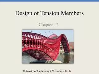
Tension Members Last Time. Structural Elements Subjected to Axial Tensile Forces. Trusses. Bracing for Buildings and Bridges. Cables in Suspension and Cable-Stayed Bridges. TENSION MEMBERS – TYPES Last Time. TENSION MEMBERS – TYPES Last Time. Structural Shapes & Build Up Members

Tension Members Last Time
E N D
Presentation Transcript
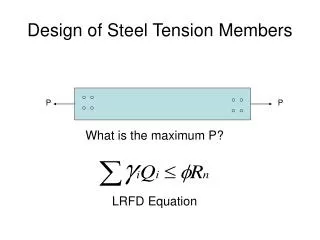
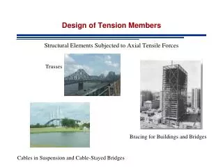
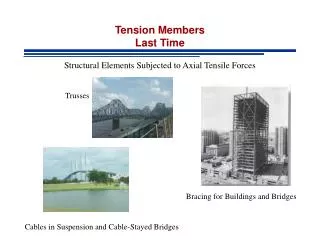
Tension MembersLast Time Structural Elements Subjected to Axial Tensile Forces Trusses Bracing for Buildings and Bridges Cables in Suspension and Cable-Stayed Bridges
TENSION MEMBERS – TYPES Last Time Structural Shapes & Build Up Members rigidity, small lateral loads, load reversal Slenderness L/r > 300 AISC Spec D1 Does not apply to rods in tension
Limit States Last Time STRENGTH • Failure at Main Body • Failure at Connection • etc
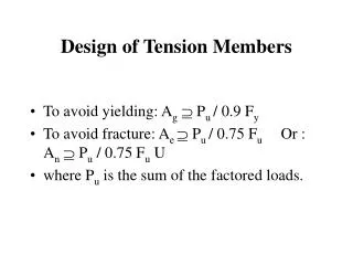
TENSION MEMBERS - LIMIT STATES AISC Specs Chapter DLast Time Failure at main body if connection is strong enough After yielding deformations become too large and member does not serve its design purpose. Failure at yielding nominal strength Pn=FyAg Fy = Yielding Strength, Ag = Gross Area
TENSION MEMBERS - LIMIT STATES AISC Specs Chapter DLast Time Failure at Connection if connection is weak it will fracture Failure at ultimate strength nominal strength Pn=FuAe Fu = Ultimate Strength, Ae = Effective Area
Gross Area – Specs D3.1 p 16.1.27 Last Time Gross Area Ag: Total Area of Main Body of Member
Net Area – Specs D3.2 p 16.1.27 Last Time Net Area An : Welded Connections An = Ag Bolded Connections An = Ag - Area of Holes
Net Area Last Time Size of hole is larger than size of the bolt dh=db +1/16” Additional 1/16” of material is damaged during drilling or punchning of holes (Commentary D3.2 p 16.1-250)
Staggered Fasteners Geometry Constraints Space Limitations
Staggered Fasteners Inclined Fracture Path
Net Area - Effect of Staggered Holes AISC Specs D3.1 Last Time T T T p Reduced diameter T g g = gage s = spacing s Failure paths on net section
Example Last Time 11 holes 8/11 of load Different failure lines may be subjected to different loads!
Net Area - Gage Distance for an Angle Unfold Angle and Visualize as a plate
Net Area - Gage Distance for an Angle For holes on different legs
Effective Net Area – Specs D3.3 p 16.1.28 Ae=AU A = Area that depends on type of connection A=Ag for welded A=An for bolted U = shear lag coefficient (accounts for eccentricities)
U Accounts for eccentricities U AISC D3.3 Table D3.1
Shear Lag Factor • General category for any type of tension member except plates and round HSS with • Plates • Round HSS with • Alternative values for single angles • Alternative values for W,M,S and HP shapes
1. General category for any type of tension member except plates and round HSS with Distance from centroid of connected area to the plane of the connection l Length of the connection
1. General category for any type of tension member except plates and round HSS with
1. General category for any type of tension member except plates and round HSS with
2. Plates U=1.0 since cross section has one element and it is connected Special Cases a. Longitudinal welds on sides only
2. Plates U=1.0 since cross section has one element and it is connected Special Cases b. Transverse welds only (uncommon) An net area of directly connected members
4. Alternative values for single angles 2 or 3 fasteners in direction of loading 4 fasteners in direction of loading
5. Alternative values for W,M,S and HP shapes Connected through flange with 3 or more fasteners in direction of loading
5. Alternative values for W,M,S and HP shapes Connected through flange with 3 or more fasteners in direction of loading
5. Alternative values for W,M,S and HP shapes Connected through web with 4 or more fasteners in direction of loading
Example Determine Effective Net Area
Example Only one element is connected Net area must be reduced
Example Alternatively 3 bolts in direction of load
Block ShearChapter D User Note -> J4.3 (p. 16.1-112) Failure occurs by rupture on the shear area and rupture on the tension area Both surfaces (shear and tension) contribute to total strength
Block ShearChapter D User Note -> J4.3 (p. 16.1-112) Both surfaces (shear and tension) contribute to total strength Anv: net shear area Ant : net tension area
Block ShearChapter D User Note -> J4.3 (p. 16.1-112) Anv: net shear area Ant : net tension area For angles and gusset plates
Block ShearChapter D User Note -> J4.3 (p. 16.1-112) Anv: net shear area Ant : net tension area AISC Ubs=1 for angles, gusset plates and most coped beams See AISC Commentary J4.3 for other less common cases
Example Compute block shear strength per LRFD and ASD
Example Nominal Strength LRFD ASD