Download
1 / 75
780 likes | 1.23k Vues
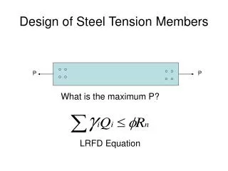
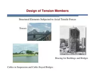
Design of Tension Members. Chapter - 2. University of Engineering & Technology, Taxila. Introduction. Members subjected to axial tensile forces are called Tension Members. These members tend to elongate on the application of load.

E N D
Design of Tension Members Chapter - 2 University of Engineering & Technology, Taxila
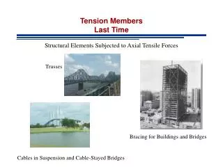
Introduction Members subjected to axial tensile forces are called Tension Members. These members tend to elongate on the application of load. Bending due to simultaneous transverse loads and buckling are significantly reduced and a initially non-straight member tends to straighten up.
Typical examples are main members of trusses subjected to tension. However, secondary members like tie rods and certain braces may also be subjected to tensile loads. In general, the use of single structural shape is more economical than the built-up section in case of a tension member.
Built-up sections may be required in the following situations: • The tensile capacity of a single rolled section is not sufficient. • The slenderness ratio (KL/r) does not provide sufficient rigidity. • The effect of bending combined with the tensile behavior requires a larger
lateral stiffness. • Unusual connection details require a particular cross-section. • Aesthetics dictates a particular cross-sectional shape.
Gross Area of Cross-Section (Ag) It is the total area of cross-section present throughout the length of the member. The elements, which are discontinued lengthwise, are not included. For example, area of lacing elements and spacer plates is not included in gross area.
The gross area for rolled steel shapes is directly available in the properties tables.
Net Area of Cross-Section (An) When tension members have holes punched in them for rivets or bolts, the minimum reduced area after the holes are taken out is called the net area. Failure of a tension member always occurs at the weakest section where area of cross-section is minimum.
Net Area of Cross-Section (An) According to AISC – D3.2, the net area of a member is the sum of the products of the thickness and the net width of each element.
t d d t
Efficiency of a joint and Shear Lag Factor (U) The bolts and welds transfer forces over smaller areas of the joining plates. These bearing and other pressures produce stress concentrations at some points within the member cross-section.
Further, eccentricity in connection may produce extra stresses due to unwanted moments. Similarly, at a connection, if one part of the section is connected while the other is left free, all the forces have to pass only through the connected part at the joint.
Away from the joint, these stresses spread to give a uniform stress distribution. Efficiency of a joint is defined as how well the stresses are distributed to transfer the applied forces. If the joint is not fully efficient, premature failure can occur reducing the member strength.
This expected reduction is usually applied on the area of cross-section to get effective net area used to calculate the reduced member strength. According to AISC Specifications, efficiency is considered 100% for all welded connections and those bolted connections where all parts of the section are connected.
Shear lag factor (U) is the factor by which net area of a section is reduced for shear lag, stress concentrations and eccentricity at the joints. Mathematically it may be written as the ratio of the effective net area (Ae) to the net area (An).
However, this expression is used in the order Ae= U An meaning that An and U are found first to calculate Ae. The approximate values of this factor for various joining conditions are given in Table D3.1 of AISC Specifications.
Some typical values are reproduced here. • When tension load is transmitted through each of the cross-sectional elements by fasteners or welds, U = 1.0 • The preferable expression for U for all tension members, except plates and HSS, where load is not transferred by all elements of the section, is as follows:
= distance from centroid of element being connected eccentrically to plane of load transfer, called connection eccentricity. L = length of connection, centre-to-centre of the outer rivet holes or actual length of weld.
Gusset Plate c.g of Angle c.g of equivalent T
L L
When tension load is transferred by transverse welds, Ae= U An Where, An = area of directly connected elements and U = 1.0
When two separate plates are connected by longitudinal welds, For lw ≥ 2B U = 1.00 For 2B > lw ≥ 1.5B U = 0.87 For 1.5B > lw ≥ B U = 0.75 Where, lw = length of weld B = width of plate equal to distance between welds
For W, M, S, HP or tees with flange connected with 3 or more fasteners per line in the direction of loading, the following values may approximately be considered. For bf ≥ 2/3d U = 0.90 For bf < 2/3d U = 0.85
For W, M, S, HP or tees with web connected with 4 or more fasteners per line in the direction of loading, U = 0.70. • For single angle section with 4 or more fasteners per line in the direction of loading U = 0.80. • For single angle section with 2 or 3 fasteners per line in the direction of loading, U = 0.60.
For double angles, the same value as given by AISC for single angles may approximately be used. For I-shaped sections, usually the shear lag factor, calculated by the given equation, becomes less than the tabulated U factor if only three rivets are used.
Hence, it is better to use 4 or more rivets in a line for such sections.
Effective Net Area (Ae) The effective net area that can be considered to resist tension at a section through the holes may be somewhat smaller than the actual net area (An) because of stress concentrations and other factors and is defined as Ae= U An
CALCULATION OF NET AREAReduction in Area for One Fastener In fabricating structural steel, which is to be connected with rivets or bolts, the holes are usually punched larger than the diameter of the rivet or bolt.
Further more, the punching of hole is assumed to damage or even destroy 0.75 mm or more of the surrounding metal beyond the drilled hole. For design, the width of a fastener hole shall be taken as 2 mm greater than the nominal dimension of the hole. The nominal holes are given in Table 2.1.
Diameter of holes considered for strength calculations = (dia. of the rivet + 1.5 + 1.5) mm = (dia. of the standard bolt hole, dh + 2) mm The diameter of hole for the rivet is d + 1.5, whereas another 1.5 mm is to be added because this extra portion around the hole may be damaged due to drilling of the hole.
The area of hole to be subtracted from width of the cross-section is rectangular and equals the diameter of the hole times the thickness of the metal. Reduction in area for one fastener = (d + 3) t for rivets = (dh + 2) t for standard bolt holes
Reduction in Area for More than One Hole Reduction in area = n (d + 3) t for rivets = n (dh + 2) t for standard bolt holes where n = number of holes in the critical failure path d = diameter of fastener, and t = thickness of plate
An = Ag – n (d+ 3) t for vertical failure plane when rivets are used. In the above expression, (d + 3)is to be replaced by (dh + 2)for standard bolt holes. AISC J4.1(b) limits An to a maximum of 0.85Ag for splice plates with holes.
Example 2.1 Determine the net area of a 10 x 200 mm plate joined with two 6 x 200 mm plates as shown in Figure 2.3. The plates are connected to each other with two lines of 20 mm rivets. Solution 10 x 200 = 2000 mm2 Ag = smaller of 2 x 6 x 200 = 2400 mm2 = 2000 mm2
T T Critical Section 10 x 200 mm plate T/2 T T/2 6 x 200 mm, 2 plates Figure 2.3. Connection of Three Plates by Rivets
T T
The failure plane is vertical having two holes in its path, n = 2, An = Ag – n (d+ 3) t = 2000 – (2) (20 + 3) (10) = 1540 mm2
Fastener Spacing Pitch of fasteners The centre-to-centre distance of the fasteners along the longitudinal axis of the member is called pitchand is denoted by p, as shown in figure 2.4.
Gage distance of fasteners The centre-to-centre distance between the fasteners along the transverse direction is called gagedenoted by g; refer to Figure 2.4. Standard gage distances for angles and channels are given in Figures 2.5 and 2.6.
Stagger of fasteners The longitudinal distance between two nearest rivets lying in two adjacent layers of rivets is called stagger denoted by s and shown in figure 2.4.
A B T T g C p s D Failure Plane = A – B – C – D Figure 2.4. Fastener Spacing in Various Directions
g2 g1 g Figure 2.5. Usual Gages for Angles
g1 g Figure 2.6. Usual Gages for Channels
Additional Area due to inclined Failure Plane Just like each hole in the path of failure plane reduces net area, area equal to is added to the net area for each inclined line in the assumed failure plane.
An = Ag – n (d+ 3) t + for rivets Total Net Area (An) Note: This area must be calculated for all possible critical failure planes and the least value must be taken. or Net width = Actual width – n (d+3) + for rivets
A typical truss connection is shown in Figure 2.5 to explain the position of gusset plate and the fasteners. Gusset plate is a plate to which all the truss members are connected at a joint.
Total Net Area for Welded Connections In case of welded members, net area and effective net area are both considered equal to the gross area with U = 1.