Download

1 / 20
250 likes | 750 Vues
Reinforced Concrete Flexural Members. Reinforced Concrete Flexural Members. Concrete is by nature a continuous material. Once concrete reaches its tensile strength ~400 psi, concrete will crack. Stress in steel will be ~ 4000 psi. Design Criteria. Serviceability Crack width limits

E N D
Reinforced Concrete Flexural Members Concrete is by nature a continuous material Once concrete reaches its tensile strength ~400 psi, concrete will crack. Stress in steel will be ~ 4000 psi.
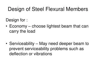
Design Criteria • Serviceability • Crack width limits • Deflection limits • Strength – must provide adequate strength for all possible loads
As area of steel in tension zone As’area of steel in compression zone d distance from center of tension reinforcement to outermost point in compression d’ distance from center of compression reinforcement to outermost point in compression
Strain εs εs> εy εs T fs fs=fy fs T cracked concrete cracked concrete jd cracked concrete cracked concrete d C C εc εc=0.003 εc fc fc=f’c fc Strain and Stress in Concrete Beams Stress c M = Tjd = Cjd where j is some fraction of the ‘effective depth’, d T = Asfs at failure, T = AsFy C = T = force in As’ and concrete
Stress in Concrete at Ultimate ACI 318 approximates the stress distribution in concrete as a rectangle 0.85f’c wide and ‘a’ high, where a = β1c. Cconcrete = 0.85f’cabw Csteel = A’s f’s Asfy = 0.85f’cabw + A’s f’s
Definitions • β1 shall be taken as 0.85 for concrete strengths f’c up to and including 4000 psi. For strengths above 4000 psi, β1 shall be reduced continuously at a rate of 0.05 for each 1000 psi of strength above 4000 psi, but β1shall not be taken less than 0.65. • bw = width of web • f’s = stress in compression reinforcement (possibly fy)
With No Compression Steel… Asfy = 0.85f’cabw For most beams, 5/6 ≤ j ≤ 19/20
Moment Equation recall, M = Tjd = Cjd and T = AsFy φ = 0.9 for flexure Mu ≤ ΦMn=0.9Tjd = 0.9Asfyjd substituting 5/6 ≤ j ≤ 19/20 0.75Asfyd ≤ Mu ≤ 0.85Asfyd
Reinforcement Ratio Reinforcement ratio for beams Compression reinforcement ratio
Design Equations For positive moment sections of T-shaped beams, and for negative moment sections of beams or slabs where ρ≤ ⅓ ρb. For negative moment sections where ρ≥⅔ρb and for positive moment sections without a T flange and with ρ≥⅔ρb. For intermediate cases where ⅓ ρb < ρ < ⅔ρb regardless of the direction of bending.
Balanced Reinforcement Ratio, ρb To insure that steel tension reinforcement reaches a strain εs ≥ fy/Es before concrete reaches ε = 0.003 (steel yields before concrete crushes) the reinforcement ratio must be less than ρb. Where ρbis the balanced reinforcement ratio or the reinforcement ratio at which the steel will yield and the concrete will crush simultaneously. For rectangular compression zones (negative bending) For positive bending (T-shaped compression zone) reinforcement ratio is usually very low (b very large) b = effective flange width, least of: bw + half distance to the adjoining parallel beam on each side of the web ¼ the span length of the beam bw + 16 hf
Balanced Reinforcement Ratio Note: if ρ > ρb can add compression reinforcement to prevent failure due to crushing of concrete.
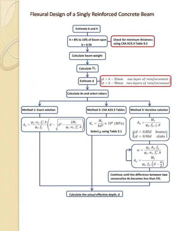
Depth of Beam for Preliminary Design The ACI code prescribes minimum values of h, height of beam, for which deflection calculations are not required.
Preliminary Design Values ρ ≤ 5/3 ρb practical maximum reinforcement ratio For typical d/bw ratios:
Beam Analysis ACI 318 Approximate Moments and Shears
Compression Reinforcement If ρ >ρb must add compression reinforcement to prevent failure due to crushing of concrete
Crack Control For serviceability, crack widths, in tension zones, must be limited. ACI 318 requires the tension reinforcement in the flanges of T-beams be distributed over an effective flange width, b, or a width equal to 1/10 span, whichever is smaller. If the effective flange width exceeds 1/10 the span, additional reinforcement shall be provided in the outer portions of the flange.
Flexure Design Example p. 21 notes The partial office building floor plan shown had beams spanning 30 ft and girders spanning 24 ft. Design the slab, beams, and girders to support a live load of 80 psf and a dead weight of 15 psf in addition to the self weight of the structure. Use grade 60 reinforcing steel and 4000 psi concrete. 30 ft 30 ft 30 ft 30 ft 24 ft 24 ft 24 ft