Chapter 8 The Routing Table: A Closer Look
920 likes | 1.08k Vues
Chapter 8 The Routing Table: A Closer Look. CIS 82 Routing Protocols and Concepts Rick Graziani Cabrillo College graziani@cabrillo.edu Last Updated: 4/14/2008. Note. My web site is www.cabrillo.edu/~rgraziani.

Chapter 8 The Routing Table: A Closer Look
E N D
Presentation Transcript
Chapter 8The Routing Table: A Closer Look CIS 82 Routing Protocols and Concepts Rick Graziani Cabrillo College graziani@cabrillo.edu Last Updated: 4/14/2008
Note • My web site is www.cabrillo.edu/~rgraziani. • For access to these PowerPoint presentations and other materials, please email me at graziani@cabrillo.edu.
For further information • This presentation is an overview of what is covered in the curriculum/book. • For further explanation and details, please read the chapter/curriculum. • Book: • Routing Protocols and Concepts • By Rick Graziani and Allan Johnson • ISBN: 1-58713-206-0 • ISBN-13: 978-58713-206-3
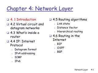
Topics • Routing Behavior • Classful and Classless Routing Behavior • Classful Routing Behavior: no ip classless • Classless Routing Behavior: ip classless • The Routing Table Structure • Topology • Routing Table Entries • Level 1 Routes • Parent and Child Routes: Classful Networks • Parent and Child Routes: Classless Networks • Routing Table Lookup Process • Steps in the Route Table Lookup Process • Longest Match: Level 1 Routes • Longest Match: Level 2 Routes
Understanding the Routing Table • Understanding the structure and lookup process of the routing table • Help you diagnose any routing table issue • Regardless of your level of familiarity with the routing protocol. • Is the packet is being forwarded as expected? Why or why not? • Forwarded elsewhere? Discarded? • For more details: Cisco IP Routing, by Alex Zinin (ISBN 0-201-60473-6)
The Routing Table Structure Router# show ip route 172.16.0.0/24 is subnetted, 4 subnets S 172.16.4.0 is directly connected, Serial0/0/1 R 172.16.1.0 [120/1] via 172.16.2.1, 00:00:08, Serial0/0/0 C 172.16.2.0 is directly connected, Serial0/0/0 C 172.16.3.0 is directly connected, FastEthernet0/0 10.0.0.0/16 is subnetted, 1 subnets S 10.1.0.0 is directly connected, Serial0/0/1 C 192.168.1.0/24 is directly connected, Serial0/0/1 S 192.168.100.0/24 is directly connected, Serial0/0/1 • The structure of the routing table might seem obvious. • Help you verify and troubleshoot routing issues because you will understand the routing table lookup process. • You will know exactly what the Cisco IOS software does when it searches for a route.
Topology • Notice that R3 also has a 172.16.4.0/24 subnet that is disconnected, or discontiguous, from the 172.16.0.0 network that R1 and R2 share. • The effects of this discontiguous subnet are examined later in this chapter when you look at the route lookup process.
Topology: Interface Configurations for R1 and R3 R1(config)# interface FastEthernet0/0 R1(config-if)# ip address 172.16.1.1 255.255.255.0 R1(config-if)# no shutdown R1(config-if)# interface Serial0/0/0 R1(config-if)# ip address 172.16.2.1 255.255.255.0 R1(config-if)# clock rate 64000 R1(config-if)# no shutdown R3(config)# interface FastEthernet0/0 R3(config-if)# ip address 172.16.4.1 255.255.255.0 R3(config-if)# no shutdown R3(config-if)# interface Serial0/0/1 R3(config-if)# ip address 192.168.1.2 255.255.255.0 R3(config-if)# no shutdown
Sample Routing Table Entries Router# show ip route 172.16.0.0/24 is subnetted, 4 subnets S 172.16.4.0 is directly connected, Serial0/0/1 R 172.16.1.0 [120/1] via 172.16.2.1, 00:00:08, Serial0/0/0 C 172.16.2.0 is directly connected, Serial0/0/0 C 172.16.3.0 is directly connected, FastEthernet0/0 10.0.0.0/16 is subnetted, 1 subnets S 10.1.0.0 is directly connected, Serial0/0/1 C 192.168.1.0/24 is directly connected, Serial0/0/1 S 192.168.100.0/24 is directly connected, Serial0/0/1 • Route entries from the following sources: • Directly connected networks • Static routes • Dynamic routing protocols • The source of the route does not affect the structure of the routing table
Sample Routing Table Entries Router# show ip route 172.16.0.0/24 is subnetted, 4 subnets S 172.16.4.0 is directly connected, Serial0/0/1 R 172.16.1.0 [120/1] via 172.16.2.1, 00:00:08, Serial0/0/0 C 172.16.2.0 is directly connected, Serial0/0/0 C 172.16.3.0 is directly connected, FastEthernet0/0 10.0.0.0/16 is subnetted, 1 subnets S 10.1.0.0 is directly connected, Serial0/0/1 C 192.168.1.0/24 is directly connected, Serial0/0/1 S 192.168.100.0/24 is directly connected, Serial0/0/1 • The routing table hierarchy in Cisco IOS software was originally implemented with the classful routing scheme. • Although the routing table incorporates both classful and classless addressing, the overall structure is still built around this classful scheme.
Level 1 Routes R2# debug ip routing IP routing debugging is on R2# conf t R2(config)# interface serial 0/0/1 R2(config-if)# ip address 192.168.1.1 255.255.255.0 R2(config-if)# clock rate 64000 R2(config-if)# no shutdown R2(config-if)# 00:11:06: %LINK-3-UPDOWN: Interface Serial0/0/1, changed state to up R2(config-if)# RT: add 192.168.1.0/24 via 0.0.0.0, connected metric [0/0] RT: interface Serial0/0/1 added to routing table R2(config-if)# end R2# undebug all All possible debugging has been turned off • Serial 0/0/1 interface for R2 is configured with the 192.168.1.1/24 address • As soon as no shutdownis entered, the output from debug ip routingshows that this route has been added to the routing table.
Level 1 Routes RT: add 192.168.1.0/24 via 0.0.0.0, connected metric [0/0] RT: interface Serial0/0/1 added to routing table R2(config-if)# end R2# show ip route <output omitted> C 192.168.1.0/24 is directly connected, Serial0/0/1 • The routing table is actually a hierarchical structure that is used to speed up the lookup process when locating routes and forwarding packets. • Within this structure, the hierarchy includes several levels. • For simplicity, we discuss all routes as one of two levels: level 1 or level 2.
Level 1 Routes R2# show ip route <output omitted> C 192.168.1.0/24 is directly connected, Serial0/0/1 • A level 1 route is a route with a subnet mask equal to or less than the classful mask of the network address. • 192.168.1.0/24 is a level 1 network route because the subnet mask is equal to the network’s classful mask. • /24 is the classful mask for Class C networks, such as the 192.168.1.0 network.
Level 1 Routes We will be using this chart throughout this chapter. • A level 1 route can function as any of the following: • Default route: A default route is a static route with the address 0.0.0.0/0. • Supernet route: A supernet route is a network address with a mask less than the classful mask. • Network route: A network route is a route that has a subnet mask equal to that of the classful mask. • A network route can also be a parent route (next).
Level 1 Routes • The level 1 route 192.168.1.0/24 can be further defined as an ultimate route. • An ultimate route is a route that includes one or both of the following: • A next-hop IP address (another path) • An exit interface
Level 1 Routes • Directly connected network 192.168.1.0/24 is a • level 1 network route - subnet mask that is the same as its classful mask. • ultimate route - contains the exit interface Serial 0/0/1.
Parent and Child Routes: Classful Networks R2(config)# interface fastethernet 0/0 R2(config-if)# ip address 172.16.3.1 255.255.255.0 R2(config-if)# no shutdown R2(config-if)# end R2# show ip route Codes: C - connected, S - static, I - IGRP, R - RIP, M - mobile, <text omitted> Gateway of last resort is not set 172.16.0.0/24 is subnetted, 1 subnets C 172.16.3.0 is directly connected, FastEthernet0/0 C 192.168.1.0/24 is directly connected, Serial0/0/1 Level 1 Parent Route Level 2 Child Route • Another type of level 1 network route, a parent route. • When the 172.16.3.0 subnet was added to the routing table, • Another route, 172.16.0.0 also added. • First entry: nonext-hop IP address or exit interface information. • This route is known as a level 1 parent route.
Parent and Child Routes: Classful Networks R2# show ip route Codes: C - connected, S - static, I - IGRP, R - RIP, M - mobile, <text omitted> Gateway of last resort is not set 172.16.0.0/24 is subnetted, 1 subnets C 172.16.3.0 is directly connected, FastEthernet0/0 C 192.168.1.0/24 is directly connected, Serial0/0/1 Level 1 Parent Route Level 2 Child Route • A parent route is a heading: • Indicates the presence oflevel 2 routes, also known as child routes. • A level 1 parent route is automatically created any time a subnet is added to the routing table. • A parent route is created whenever a route with a mask greater than the classful mask is entered into the routing table. • The subnet 172.16.3.0 is the level 2 child route of the parent route172.16.0.0.
Parent and Child Routes: Classful Networks Level 1 Parent Route Level 2 Child Route • A level 2 route is a route that is a subnet of a classful network address. • Like a level 1 route, the source of a level 2 route can be a : • directly connected network • static route • dynamic routing protocol. • Note: This is the case even if a classless routing protocol is the source of the subnet route.
Parent route: • 172.16.0.0: The classful network address for our subnet. • /24: The subnet mask for all the child routes. If the child routes have variable-length subnet masks (VLSM), the subnet mask will be excluded from the parent route and included with the individual child routes. (later). • is subnetted, 1 subnets: This part of the route specifies that this is a parent route and in this case has one child route (that is, one subnet).
Child route: • C: The route code for a directly connected network. • 172.16.3.0: The specific route entry. • is directly connected: Along with the route code of C, this specifies that this is a directly connected network with an administrative distance of 0. • FastEthernet0/0: The exit interface for forwarding packets that match this specific route entry.
A level 2 child routecontains the route source and the network address of the route. • Notice that the subnet mask is not included with the subnet, the level 2 child route. • The subnet mask for this child route is the /24 mask included in its parent route, 172.16.0.0. • Level 2 child routes are also considered ultimate routes because they contain the next-hop IP address or exit interface.
Adding another child route R2(config)# interface serial 0/0/0 R2(config-if)# ip address 172.16.2.2 255.255.255.0 R2(config-if)# no shutdown R2(config-if)# end R2# show ip route 172.16.0.0/24 is subnetted, 2 subnets C 172.16.2.0 is directly connected, Serial0/0/0 C 172.16.3.0 is directly connected, FastEthernet0/0 C 192.168.1.0/24 is directly connected, Serial0/0/1 • The routing table shows two child routes for the same 172.16.0.0/24 parent route. • 172.16.2.0 and 172.16.3.0 are members both members of the 172.16.0.0/16 classful network. • Because both child routes have the same subnet mask, the parent route still maintains the /24 mask but now shows two subnets. • Later we will see the role of the parent route.
Adding another child route If child routes are deleted there is no parent route. • If there is only a single level 2 child route and that route is removed, the level 1 parent route is automatically deleted. • A level 1 parent route exists only when there is at least one level 2 child route.
Parent and Child Routes: Classless Networks • For this discussion, we switch briefly to the RouterX topology.
Parent and Child Routes: Classless Networks RouterX# show ip route 172.16.0.0/16 is variably subnetted, 3 subnets, 2 masks C 172.16.1.4/30 is directly connected, Serial0/0/0 C 172.16.1.8/30 is directly connected, Serial0/0/1 C 172.16.3.0/24 is directly connected, FastEthernet0/0 • All three subnets belong to the classful network 172.16.0.0/16 and are therefore level 2 child routes. • Notice that the child routes do not share the same subnet mask, as was the case in the classful example. • Implementing a network addressing scheme with VLSM. • Whenever there are two or more child routes with different subnet masks belonging to the same classful network, the routing table presents a slightly different view, which states that this parent network is variably subnetted.
Parent and Child Routes: Classless Networks • The parent route of 172.16.0.0 now contains the classful mask /16. • In the classful example shown earlier the classful mask was not displayed. • Parent route states that the child routes are variably subnetted. • Includes the number of different masks of the child routes (2 masks). • Each child route now contains the subnet mask for that specific route. • In the non-VLSM example both child routes shared the same subnet mask, and the parent displayed their common subnet mask.
Parent route: • 172.16.0.0: The parent route, the classful network address associated with all child routes • /16: The classful subnet mask of the parent route • variably subnetted: States that the child routes are variably subnetted and that there are multiple masks for this classful network • 3 subnets, 2 masks: Indicates the number of subnets and the number of different subnet masks for the child routes under this parent route
Child route: • C: The route code for a directly connected network • 172.16.1.4: The specific route entry • /30: The subnet mask for this specific route • is directly connected: Along with the route code of C, specifies that this is a directly connected network with an administrative distance of 0 • Serial0/0/0: The exit interface for forwarding packets that match this specific route entry
Routing Table Lookup Process IP Packet Routing Table • When a router receives a packet on one of its interfaces. • The routing table lookup process compares the destination IP address of the incoming packet with the entries in the routing table. • The best match between the packet’s destination IP address and the route in the routing table is used to determine to which interface to forward the packet. Find “best match”
Steps in the Route Table Lookup Process R1(config)# router rip R1(config-router)# network 172.16.0.0 R2(config)# router rip R2(config-router)# network 172.16.0.0 R2(config-router)# network 192.168.1.0 R3(config)# router rip R3(config-router)# network 172.16.0.0 R3(config-router)# network 192.168.1.0 • We have specifically chosen a classful routing protocol with our discontiguous 172.16.0.0 subnets. • The reason for this will become evident in a later section.
Steps in the Route Table Lookup Process R1# show ip route 172.16.0.0/24 is subnetted, 3 subnets C 172.16.1.0 is directly connected, FastEthernet0/0 C 172.16.2.0 is directly connected, Serial0/0/0 R 172.16.3.0 [120/1] via 172.16.2.2, 00:00:25, Serial0/0/0 R 192.168.1.0/24 [120/1] via 172.16.2.2, 00:00:25, Serial0/0/0 R2# show ip route 172.16.0.0/24 is subnetted, 3 subnets R 172.16.1.0 [120/1] via 172.16.2.1, 00:00:07, Serial0/0/0 C 172.16.2.0 is directly connected, Serial0/0/0 C 172.16.3.0 is directly connected, FastEthernet0/0 C 192.168.1.0/24 is directly connected, Serial0/0/1 • Neither R1 nor R2 has a route to 172.16.4.0. • Also, R3 does not have routes to subnets 172.16.1.0/24, 172.16.2.0/24, or 172.16.3.0/24. R3# show ip route 172.16.0.0/24 is subnetted, 1 subnets C 172.16.4.0 is directly connected, FastEthernet0/0 C 192.168.1.0/24 is directly connected, Serial0/0/1
The Route Lookup Process Routing Table Step 1. • The router examines level 1 routes, including network routes and supernet routes, for the best match with the destination address of the IP packet
The Route Lookup Process Routing Table Step 1a. • If the best match is a level 1 ultimate route—a classful network, supernet, or default route—this route is used to forward the packet
The Route Lookup Process Routing Table Step 1b. • If the best match is a level 1 parent route, proceed to Step 2
The Route Lookup Process Routing Table Step 2. • The router examines child routes (the subnet routes) of the parent route for a best match.
The Route Lookup Process Routing Table Step 2a. • If there is a match with a level 2 child route, that subnet is used to forward the packet.
The Route Lookup Process Routing Table Step 2b. • If there is not a match with any of the level 2 child routes, proceed to Step 3.
The Route Lookup Process Routing Table Step 3. • Is the router implementing classful or classless routing behavior. (later) • Router(config)# no ip classless • Router(config)# ip classless
The Route Lookup Process Routing Table Step 3a. • If classful routing behavior is in effect, terminate the lookup process and drop the packet. • Router(config)# no ip classless
The Route Lookup Process Routing Table Step 3b. • If classless routing behavior is in effect, continue searching level 1 supernet routes in the routing table for a match, including the default route, if there is one.
The Route Lookup Process Routing Table Step 4. • If there is now a lesser match with a level 1 supernet or default routes, the router uses that route to forward the packet.
The Route Lookup Process Routing Table Step 5. • If there is not a match with any route in the routing table, the router drops the packet.
Longest Match • (Digressing from topology) • For there to be a match between the destination IP address of a packet and a route in the routing table,a minimum number of leftmost bits must match between the IP address of the packet and the route in the routing table. • The subnet mask of the route in the routing table is used to determine the minimum number of leftmost bits that must match. • IP packetonly contains the IP address and not the subnet mask.
Longest Match • The best match or longest match is the route in the routing table that has the greatest number of leftmost matching bits with the destination IP address of the packet. • The route with the greatest number of equivalent leftmost bits, or the longest match, is always the preferred route. • Subnet mask in routing table specifies the minimum number of leftmost matching bits – the only bits that are considered. All three routes match but Route 3 has the longest match.
Example: Level 1 Ultimate Route • PC1 sends a ping to 192.168.1.2, the serial interface on R3. R1# show ip route 172.16.0.0/24 is subnetted, 3 subnets C 172.16.1.0 is directly connected, FastEthernet0/0 C 172.16.2.0 is directly connected, Serial0/0/0 R 172.16.3.0 [120/1] via 172.16.2.2, 00:00:25, Serial0/0/0 R 192.168.1.0/24 [120/1] via 172.16.2.2, 00:00:25, Serial0/0/0
192.168.1.2 • The router first examines level 1 routes for the best match. R1# show ip route 172.16.0.0/24 is subnetted, 3 subnets R 192.168.1.0/24 [120/1] via 172.16.2.2, 00:00:25, Serial0/0/0