Network Layer
Shahrood University of Technology Department of Computer Engineering & IT. Computer Networks. Network Layer. Chapter 4 Outline. 4.1 Introduction and Network Service Models 4.2 Routing Principles 4.3 Hierarchical Routing 4.4 The Internet (IP) Protocol 4.5 Routing in the Internet

Network Layer
E N D
Presentation Transcript
Shahrood University of TechnologyDepartment of Computer Engineering & IT Computer Networks Network Layer
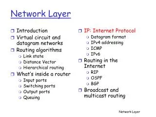
Chapter 4 Outline 4.1 Introduction and Network Service Models 4.2 Routing Principles 4.3 Hierarchical Routing 4.4 The Internet (IP) Protocol 4.5 Routing in the Internet 4.6 What’s Inside a Router 4.7 IPv6 4.8 Multicast Routing 4.9 Mobility
transport packet from sending to receiving hosts network layer protocols in every host, router three important functions: path determination: route taken by packets from source to dest. (Routing Algorithms) forwarding: move packets from router’s input to appropriate router output call setup: some network architectures require router call setup along path before data flows network data link physical network data link physical network data link physical network data link physical network data link physical network data link physical network data link physical network data link physical Network Layer Functions application transport network data link physical application transport network data link physical
Q: What service model for “channel” transporting packets from sender to receiver? Services guaranteed bandwidth? preservation of inter-packet timing (no jitter)? loss-free delivery? in-order delivery? congestion feedback to sender? Network Service Model The most important abstraction provided by network layer: virtual circuit or datagram?
call setup, teardown for each call before data can flow each packet carries VC identifier (not destination host ID) every router on source-destination path maintains “state” for each passing connection transport-layer connection only involved two end systems Link and router resources (bandwidth, buffers) may be allocated to VC to get circuit-like performance. “source-to-destination path behaves much like telephone circuit” performance-wise network actions along source-to-destination path Virtual circuits
used to setup, maintain teardown VC used in ATM, frame-relay, X.25 not used in today’s Internet application transport network data link physical application transport network data link physical Virtual Circuits: Signaling Protocols 6. Receive data 3. Accept call 2. Incoming call 5. Data flow begins 4. Call connected 1. Initiate call
no call setup at network layer routers: no state about end-to-end connections no network-level concept of “connection” packets forwarded using destination host address packets between same source-destination pair may take different paths application transport network data link physical application transport network data link physical Datagram networks: the Internet model 2. Receive Data 1. Send Data
Network Layer Service Models: Guarantees ? Congestion feedback no (inferred via loss) no congestion no congestion yes no Network Architecture Internet ATM ATM ATM ATM Service Model best effort CBR VBR ABR UBR Bandwidth none constant rate guaranteed rate guaranteed minimum none Loss no yes yes no no Order no yes yes yes yes Timing no yes yes no no CBR: Constant bit rate VBR: Variable bit rate ABR: Available bit rate UBR: Unspecified bit rate • Internet model being extended: Integrated services, Differentiated Services • Chapter 6
QoS Factors • Timing • Connection Establishment Delay • End-To-End Delay • Connection Establishment Failure Probability • Throughput or Bandwidth Guarantee • Ordering Preservation • Congestion Indication (Control) • Bit-Error rate or Packet-Loss Rate Control • Protection • Priority • Resilience (Return Back to Normal Operation).
Service Clases • Guaranteed Quality of Service • Predictive Quality of Service • Best Effort Quality of Service
Guaranteed QoS • Specified through QoS parameter values • deterministic • statistical • Single value - average (threshold, target) • Pair of values - interval • Triple of values – max., mean, min.
Predictable Service • Parameter bounds based on history, that is, past network behavior. • Parameter values are measured, and certain statistical analyses may be carried out
Best Effort Services • No guarantees of quality, no QoS parameter values • UDP/IP • Partial guarantees, some QoS parameter values are given. • TCP/IP
Internet data exchange among computers “elastic” service, no strict timing req. “smart” end systems (computers) can adapt, perform control, error recovery simple inside “network”, complexity at “edge” many link types different characteristics uniform service is difficult ATM evolved from telephony human conversation: strict timing, reliability requirements need for guaranteed service “dumb” end systems telephones complexity inside network Datagram or VC Network: why?
Active Queue Management (AQM) • Performance Degradation in current TCP Congestion Control • Multiple packet loss • Low link utilization • Congestion collapse • The role of the router (i.e., network) • Control congestion effectively with a network • Allocate bandwidth fairly
Network Interface Buffering in IP routers • Buffer size • Space for bursts of packets • Latency Internet Router Router • Dropping packets • When? • What?
FIFO Queueing in the Router(Drop Tail) Network Interface • Single queue maintained
FIFO Queueing in the Router (Drop Tail) Network Interface • Single queue maintained • Dequeue from head
FIFO Queueing in the Router (Drop Tail) Network Interface • Single queue maintained • Dequeue from head • Enqueue at tail
FIFO Queueing in the Router (Drop Tail) Network Interface • Single queue maintained • Dequeue from head • Enqueue at tail • When full
FIFO Queueing in the Router (Drop Tail) Network Interface • Single queue maintained • Dequeue from head • Enqueue at tail • When full drop arriving packet (drop-tail)
Active Queue Management • Goals: • Better congestion notification for responsive flows (i.e. TCP) • Maintain shorter queues • Fairness in drops (proportional)
Drop probability Max Queue Size Average queue length Forced drop Max Threshold Probabilistic drops Min Threshold No drops Time Active Queue ManagementRandom Early Detection (RED)
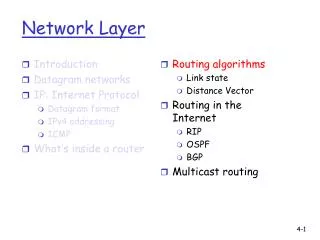
Chapter 4 Outline 4.1 Introduction and Network Service Models 4.2 Routing Principles • Link state routing • Distance vector routing 4.3 Hierarchical Routing 4.4 The Internet (IP) Protocol 4.5 Routing in the Internet 4.6 What’s Inside a Router 4.7 IPv6 4.8 Multicast Routing 4.9 Mobility
Graph abstraction for routing algorithms: graph nodes are routers graph edges are physical links link cost: delay, $ cost, or congestion level 5 3 C B 2 5 3 A 1 2 F 1 2 E D Routing protocol 1 Routing Goal: determine “good” path (sequence of routers) thru network from source to dest. Abstract model of a network • “good” path: • typically means minimum cost path • other definitions possible
1. Global: all routers have complete topology, link cost info “link state” algorithms 2. Decentralized: router knows physically-connected neighbors, link costs to neighbors iterative process of computation, exchange of info with neighbors “distance vector” algorithms 1. Static: routes update slowly over time 2. Dynamic: routes update more quickly periodic update in response to link cost changes Routing Algorithm Classifications
Dijkstra’s algorithm (global) net topology, link costs known to all nodes accomplished via “link state broadcast” all nodes have same information computes least cost paths from one node (‘source”) to all other nodes gives routing table for that node iterative: after k iterations, know least cost path to k destinations. A Link-State Routing Algorithm
5 5 3 C B 2 5 3 A 1 2 3 F 1 2 E D 1 Notation: • N: set of nodes whose least cost path definitively known c(i,j): link cost from node i to j. cost infinite if not direct neighbors • p(v): nodes along path from source to v • D(v): current value of cost of path from source to destination v. Example: N: A, B, C, D, E, F C(A,C)=5; C(C,A)=5 C(B,D)=2; C(D,B)=3 … Source=A p(F): A-D-E-F D(F)=4
v c(w,v) D(v) w A D(w) Dijsktra’s Algorithm 1 Initialization: 2 N = {A} 3 for all nodes v 4 if v adjacent to A 5 then D(v) = c(A,v) 6 else D(v) = infinity 7 8 Loop 9 find w not in N such that D(w) is a minimum 10 add w to N 11 update D(v) for all v adjacent to w and not in N: 12 D(v) = min( D(v),D(w) + c(w,v) ) 13 /* new cost to v is either old cost to v or known 14 shortest path cost to w plus cost from w to v */ 15 until all nodes in N n = number of nodes (except the source) n(n+1)/2) times
5 3 C B 2 5 3 A 1 2 F 1 2 E D 1 Dijkstra’s Algorithm: example computes least cost paths from node A to all other nodes D(F),p(F) infinity infinity 4,A-D-E-F 4,A-D-E-F 4,A-D-E-F 4,A-D-E-F D(C),p(C) 5,A-C 4,A-D-C 3,A-D-E-C 3,A-D-E-C 3,A-D-E-C 3,A-D-E-C D(B),p(B) 2,A-B 2,A-B 2,A-B 2,A-B 2,A-B 2,A-B D(E),p(E) infinity 2,A-D-E 2,A-D-E 2,A-D-E 2,A-D-E 2,A-D-E Step 0 1 2 3 4 5 start N A AD ADE ADEB ADEBC ADEBCF D(D),p(D) 1,A-D 1,A-D 1,A-D 1,A-D 1,A-D 1,A-D D(v): Distance (cost) of A to v. P(v): nodes along path fromA to v.
1 1+e 0 0 0 e 1 1 e Fig. a- Initial routing A D B C Dijkstra’s Algorithm: discussion2 Oscillations possibility: • Suppose link costs are equal to the load carried on the link, or the delay that experienced. • Link costs are not symmetric, c(A,B) equals c(B,A) only if the load on both directions on the AB link is the same. • Nodes B and D originates a unit of traffic destined for A. • Node C originates e unit for A.
1 1+e 0 0 0 e 1 2+e 0 1 1+e 1 e 0 0 Fig. a- Initial routing A A D D B B 1 1 e C C Fig. b- B, C find better path to A is clockwise Discussion2 (cont.) … oscillations possible: • Algorithm is run:C determines (Fig. a) the clockwise path to A has a cost of 1, while the counterclockwise path to A has a cost of 1 + e. Hence C ’s least-cost path to A is now clockwise. • Similarly, B determines that its new least-cost path to A is also clockwise, resulting in costs shown in Fig. b.
0 2+e 0 0 2+e 0 1 1 1 1+e 1+e 1 e 0 0 Fig. c- B, C, D find better path to A is counterclockwise A A D D B B 1 1 C C e Discussion2 (cont.) … oscillations possible: • When algorithm is run next, nodes B, C, and D all detect a zero-cost path to A in the counterclockwise direction, and all route their traffic to the counterclockwise routes. • The next time the LS algorithm is run, B, C, and D all then route their traffic to the clockwise routes. Fig. d- B, C, D find better path to A is clockwise
Dijkstra’s Algorithm: discussion2 To prevent such oscillations: • Solution1 :link costs not depend on the amount of traffic carried ,an unacceptable solution since one goal of routing is to avoid highly congested (for example, high-delay) links. • Solution2 :all routers do not run the LS algorithm at the same time (a reasonable solution). • Routers run the LS algorithm with the same periodicity, the execution instance of the algorithm would not be the same at each node. • Researchers have noted: Routers in the Internet can self-synchronize among themselves. That is, even though they initially execute the algorithm with the same period but at different instants of time, the algorithm execution instance can eventually become, and remain, synchronized at the routers. • Avoid such self-synchronization: Introduce randomization into the period between execution instants of the algorithm at each node.
Iterative: continues until no nodes exchange info. self-terminating: no “signal” to stop Asynchronous: nodes need not exchange info/iterate in lock step! distributed: each node communicates only with directly-attached neighbors Distance Table data structure each node has its own: row for each possible destination column for each directly-attached neighbor to node example: in node X, for dest. Y via neighbor Z: DX(Y,Z) X Z D (Y,Z) c(X,Z) + min {D (Y,w)} = w Distance Vector Routing Algorithm (Decentralized) distance from X to Y, via Z as next hop
E D(i, j) Distance table: A 1 B 7 A D (A,C) 2 D (A,B)= 8 E C D E B 1 c(E,B) + min {D (A,w)} = D B 2 E 8 + 6 = 14 c(E,B) … C E’s neighbor B’s neighbor Distance Table: example neighbor: j A B C D A 1 7 6 4 B 14 8 9 11 D 5 5 4 2 destination: i source B w =
Distance table gives routing table cost to destination via E Outgoing link to use, cost A,1 D,5 D,4 D,4 D () A B C D A B C D E A 1 7 6 4 B 14 8 9 11 D 5 5 4 2 D () destination destination Distance table Routing table of node E
Iterative, asynchronous: each local iteration caused by: local link cost change message from neighbor: its least cost path change from neighbor Distributed: each node notifies neighbors only when its least cost path to any destination changes neighbors then notify their neighbors if necessary Distance Vector Routing: overview wait for (change in local link cost or message from neighbor) recompute distance table if least cost path to any destination has changed, notify neighbors Each node:
Chapter 4 Outline 4.1 Introduction and Network Service Models 4.2 Routing Principles 4.3 Hierarchical Routing 4.4 The Internet (IP) Protocol 4.5 Routing in the Internet 4.6 What’s Inside a Router 4.7 IPv6 4.8 Multicast Routing 4.9 Mobility
scale: with 200 million destinations (hosts): can’t store all dest’s in routing tables (memory limitation)! routing table exchange would leave no bandwidth left for sending data packets! DV algorithm that iterated among large number of routers never converge! administrative autonomy: internet = network of networks each network admin may want to control routing in its own network Hierarchical Routing The routing study thus far was idealized • all routers identical • network “flat” … not true in practice
aggregate routers into regions, “autonomous systems” (AS) routers in same AS run same routing protocol “intra-AS” routing protocol routers in different AS can run different intra-AS routing protocol special routers in AS run intra-AS routing protocol with all other routers in AS also responsible for routing to destinations outside AS run inter-AS routing protocol with other gateway routers gateway routers Hierarchical Routing
b b b d C.b A.a A.c B.a a c a a c Intra-AS Routing Algorithm Inter-AS Routing Algorithm Routing Table DL DL DL PHL PHL PHL To/from B.a and A.a To/from A.b Intra-AS and Inter-AS routing • Gateways: • perform inter-AS routing amongst themselves • perform intra-AS routers with other routers in their AS C B A ▪Routers in an AS have information about routing paths within that AS. Inter/intra-AS routing in gateway A.c To/from A.d
A.c B.a A.a C.b b a b b d a c a c Intra-AS and Inter-AS routing Inter-AS routing between A and B Host2 B C Intra-AS routing within AS B A Intra-AS routing within AS A Host1
Chapter 4 outline 4.1 Introduction and Network Service Models 4.2 Routing Principles 4.3 Hierarchical Routing 4.4 The Internet (IP) Protocol • 4.4.1 IPv4 addressing • 4.4.2 Moving a datagram from source to destination • 4.4.3 Datagram format • 4.4.4 IP fragmentation • 4.4.5 ICMP: Internet Control Message Protocol • 4.4.6 DHCP: Dynamic Host Configuration Protocol • 4.4.7 NAT: Network Address Translation 4.5 Routing in the Internet 4.6 What’s Inside a Router 4.7 IPv6 4.8 Multicast Routing 4.9 Mobility
Host, Router network-layer-functions: Transport layer: TCP, UDP • IP protocol • addressing conventions • datagram format • packet handling conventions • Routing protocols • path selection • RIP, OSPF, BGP Network layer forwarding table • ICMP protocol • error reporting • router “signaling” Link layer physical layer The Internet Network layer ICMP: Internet Control Message Protocol, RFC792
Internet Routing Protocol • Intra-AS: administrator responsible for choice of routing algorithm within network • Also known as Interior Gateway Protocols (IGP) • Most common Intra-AS routing protocols: • RIP: Routing Information Protocol (RFCs1058,2453) • It is a distance vector protocol. • Routing updates are exchanged between neighbors app. Every 30sec. • OSPF: Open Shortest Path First (RFC2328) (Open Spec.) • IGRP: Interior Gateway Routing Protocol (Cisco proprietary) • These are link-state protocol that uses flooding of link information and a Dijkstra least-cost path algorithm. • Inter-AS: unique standard for inter-AS routing: BGP (RFC1771)
IP address: 32-bit identifier for host, router interface interface: connection between host/router and physical link router’s typically have multiple interfaces host may have multiple interfaces IP addresses associated with each interface 223.1.1.2 223.1.2.1 223.1.3.27 223.1.3.1 223.1.3.2 223.1.2.2 IP Addressing: Introduction 223.1.1.1 223.1.1.4 223.1.2.9 223.1.1.3 223.1.1.1 = 11011111 00000001 00000001 00000001 223 1 1 1
IP address: network part (high order bits) host part (low order bits) What’s a network ? (from IP address perspective) device interfaces with same network part of IP address can physically reach each other without intervening router IP Addressing 223.1.1.1 223.1.2.1 223.1.1.2 223.1.1.4 223.1.2.9 223.1.2.2 223.1.3.27 223.1.1.3 LAN 223.1.3.2 223.1.3.1 network consisting of 3 IP networks
How to find the networks? Detach each interface from router, host create “islands of isolated networks IP Addressing 223.1.1.2 223.1.1.1 223.1.1.4 223.1.1.3 223.1.7.0 223.1.9.2 223.1.9.1 223.1.7.1 223.1.8.1 223.1.8.0 223.1.2.6 223.1.3.27 Interconnected system consisting of six networks. 223.1.2.1 223.1.2.2 223.1.3.1 223.1.3.2