Collimators
Collimators. R. Assmann, CERN/AB 5/3/2008 Acknowledgements to many experts from collimation, MP, injection, dump. Extended LTC. Outline. Introduction Collimation in procedures General strategy for safe commissioning and operation Beam based collimator calibration


Collimators
E N D
Presentation Transcript
Collimators R. Assmann, CERN/AB 5/3/2008 Acknowledgements to many experts from collimation, MP, injection, dump. Extended LTC
Outline • Introduction • Collimation in procedures • General strategy for safe commissioning and operation • Beam based collimator calibration • Commissioning Preparations: Settings, Ramp, Orbit, Squeeze • Conclusion
System Design “Phase 1” Momentum Cleaning Betatron Cleaning Outcome of accelerator physics + energy deposition optimization
Aspects of Collimator Commissioning • Beam commissioning of collimators will involve many aspects: • Proton losses around the ring. • Energy deposition in accelerator devices, including SC magnets. • Quenches induced by beam loss. • Activation. • Radiation. • Background in the experiments. • Vacuum and heating in the collimation regions. • Cooling capacity. • All has been addressed over the last 5 years (CWG web site). • These issues are all driven by collimator settings (~500 degrees of freedom) and performance. • In this talk, focus on how to commission settings and performance.
Outline • Introduction • Collimation in procedures • General strategy for safe commissioning and operation • Beam based collimator calibration • Commissioning Preparations: Settings, Ramp, Orbit, Squeeze • Conclusion
Collimation in Procedures • Collimation set-up has been fully included in procedures. • Less effort initially (low intensity), more effort later (high intensity). • Collimation is a fully intensity-driven system. • Quickly run through procedure summary from Roger to illustrate well defined logic.
1 b Get going… First set-up of beam dump and injection protection. No collimation.
43 b 156 b
IR Set-Up, Two Beams, 450 GeV Collisions 1 b 156 b
Ramp and Top Energy Setup 1 - 156 b
Collision, Squeeze, Physics 1 - 156 b
Outline • Introduction • Collimation in procedures • General strategy for safe commissioning and operation • Beam based collimator calibration • Commissioning Preparations: Settings, Ramp, Orbit, Squeeze • Conclusion
Different Possible Strategies • Empirical strategy (LEP, HERA, SLC, PEP2, …) : • Tuning of collimators until observable (background) is OK, whenever needed. • Use of reference positions (reproducibility). • Regular operator interactions. • Deterministic strategy with frequent collimator set-up (Tevatron, RHIC): • Automatic calibration of collimators with respect to beam for every fill. • Observable is collimator-induced beam loss signal during set-up. • Movement to target positions. No special demands on reproducibility. • No changes from operators. Only experts. • Deterministic strategy with infrequent collimator set-up (LHC): • Calibration of collimators with respect to beam once needed. • Observable is collimator-induced beam loss signal during set-up. • Use of reference positions (reproducibility is crucial). • No changes from operators. Only experts.
Why Deterministic Strategy? • Example Tevatron (my understanding): • 1st generation collimation: • Tuning approach was used. • Too much time spent in tuning effort. • Risk of quenches and collimator damage with wrong operations by non-experts. • Collimators found in wrong positions during accidents (e.g. reduce losses by opening protection collimator – missing protection when accident occured). • 2nd generation collimation: • Clear hierarchy defined in multi-stage cleaning system. • Deterministic approach with automatic calibration of collimator position with respect to beam for every fill. • Automatic procedure: Much faster and results reproducible. • Less risk with only experts adjusting basic settings.
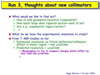
Multi-Stage Cleaning & Protection LHC Beam axis Beam propagation Impact parameter Collimator Core Particle Unavoidable losses Primary halo (p) Secondary halo p p Shower p Tertiary halo Impact parameter ≤ 1 mm p e p Primary collimator Secondary collimator Shower e SC magnets and particle physics exp. Absorber Super-conducting magnets Absorber W/Cu W/Cu CFC CFC
Settings for LHC Collimation and Protection Elements • Clear requirements for settings:LHC ring aperture sets scale aring tight LHC apertureProtection devices must protect ring aperture aprot < aring protect against injected beam; take into account accuraciesSecondary collimators tighter than protection asec < aprot avoid too much secondary halo hitting protection devicesPrimary collimators tighter than secondary aprim < asec primary collimators define the aperture bottleneck in the LHC for cleaning of circulating beam! • These conditions should always be fulfilled: Not allowed to use protection devices (or warm aperture limits) as a single-stage cleaning system! Chamonix 2005
450 GeV Settings (in sb ,d=0) aabs = ~ 10.0 sCleaning: Active absorbers in IR3 and IR7 asec3 = 9.3 sd cleaning: secondary collimators IR3 (H) aprim3 = 8.0 sd cleaning: primary collimators IR3 (H) aring = 7.5 s Ring cold or warm aperture aprot≥7.0 sDump (H) protection IR6 (TCDQ + TCS) aprot = 6.8 s Injection (V) protection IR2/IR8 (TDI, TCLI) asec = 6.7 sb cleaning: secondary collimators IR7 aprim = 5.7 sb cleaning: primary collimators IR7 aTL = 4.5 s Transfer line collimators (ring protection at 6.9 s) Tight settings below “canonical” 6/7 s collimation settings! Color code: Green – robust Blue – cold aperture Red – non-robust
7 TeV Settings at (in sb ,d=0, nominal b*) Chamonix 2005 aabs = ~ 20.0 sCleaning:Active absorbers in IR3 asec3 = 18.0 sd cleaning:secondary collimators IR3 (H) aprim3 = 15.0 sd cleaning:primary collimators IR3 (H) aabs = ~ 10.0 sCleaning:Active absorbers in and IR7 aring = 8.4 s Triplet cold aperture aprot = 8.3 s TCT protection and cleaning at triplet aprot≥7.5 sDump (H) protection IR6 (TCDQ + TCS) asec = 7.0 sb cleaning: secondary collimators IR7 aprim = 6.0 sb cleaning: primary collimators IR7 “Canonical” 6/7 s collimation settings are achievable! Color code: Green – robust Blue – cold aperture Red – non-robust
Safe System Setup • Settings hierarchy has been defined and agreed since 2005 and must absolutely be respected for guaranteeing passive protection. • Ad-hoc empirical tuning is not foreseen. High risks: • For example, background issues in IR1: • Move a TCT collimator in IR1 by 1s closer to the beam. • Assume effect on background is beneficial. New setting is kept. • Asynchronous beam dump can put beam onto TCT, now below TCDQ setting. • W jaw can be destroyed with possibility of water leak into the vacuum system. • For example, loss issues in IR6: • Open TCDQ and TCS to move out of secondary beam halo. • Losses will be reduced and setting is kept. • Compromised protection only seen in first beam dump. Damage possible. • For example, losses in IR7 dispersion suppressor: • Reduce losses by placing orbit bump with opposite sign of dispersion offsets. • Reduced aperture on the other side only seen with first high loss event. • Problems must always be addressed with coherent set of settings. Serious damage to collimation system or machine possible in the LHC. Tevatron and HERA have damaged their collimators at 200 times less stored energy. Even minor errors with damage to a few collimators will cause significant downtime (several weeks, happened in Tevatron). Major errors can mean many months of downtime for the LHC. Can restrict access to collimator control but some operational freedom must be maintained, at least for experts. Coherent setup of utmost importance!
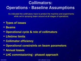
IR1 Tertiary Collimation TCTH TCTVA TAN p beam (incoming) ATLAS Very efficient but delicate protection: W jaws!
How to Guarantee Safe Collimation & Passive Protection Operational setup, tuning and changes, if required (low intensity). Machine reference status generated. Central knowledge about all changes to collimation system is established Experts come in: collimation, injection/dump protection, … YES Collimation equipment experts (ATB, CO) for interventions on collimator or collimator control. Collimation first line expert comes in and takes decision if collimation is compromised. Collimator calibration and system setup at low intensity. MACHINE CHANGECOLLIMATION PROBLEM NO Operation observes machine and maintains reference status within tolerances. Operation responsible. Collimation & passive protection declared safe for reference status (within tolerances). Experts responsible. Next commissioning step. Many possibilities – this one would work and works in RHIC and Tevatron.
Safe Collimation and Passive Protection • Experts will declare collimation and passive protection set-up safe and assume responsibility for adequate settings. • Example commitment: “Collimator settings in reference xxx are safe up to an intensity of yyy, as long as the machine is maintained according to reference zzz within tolerances. The tolerances are as follows: …” • Machine reference includes energy, orbit and optics. Tolerances will be specified for each setup. • If the machine status runs out of tolerance or collimators are moved, the machine becomes potentially unsafe. • Responsibility of operation to identify change in machine status and correct situation or call in experts. • Now, what are the tolerances?
Example Set of Tolerances • Example: 1013 protons at 7 TeV, b* = 2m • Total tolerance budget: 1.6 s • Example split (must be adjusted with experience): • Allowed change in orbit: 1.0 s ~0.2 mm (at collimators) • Allowed change in beta: 0.6 s ~ 20% • Other local constraints apply (orbit at dump kickers in IR6). • Less tolerance budget with full squeeze and high intensity. • Formalism exists for evaluating the tolerances available for operation.
People Behind(Not Formal - Snapshot) • In order that this system can work, at least one collimation expert must always be available for fast follow-up during commissioning. Later transfer to operations. • First line experts must have deep understanding of the collimation system and beams. They guarantee at all times that settings are coherent and safe: • R. Assmann (ABP) – S. Redaelli (OP) • M. Jonker (CO) – ? (ideally FLUKA expert from ATB, or BT) • Special system functions treated in collaboration with other teams: • Injection protection settings: V. Kain, B. Goddard, … • Dump protection settings: B. Goddard, J. Uythoven, … • Ions: G. Bellodi, J. Jowett • Protons: C. Bracco, T. Weiler • Background & scraping: H. Burkhardt • TOTEM: TOTEM physicists • Evident: Disconnected activities from separate teams will compromise safety and leave no one responsible in the end. I think there is agreement on this.
Outline • Introduction • Collimation in procedures • General strategy for safe commissioning and operation • Beam based collimator calibration • Commissioning Preparations: Settings, Ramp, Orbit, Squeeze • Conclusion
Beam-based Collimator Setup ~ 24 h per beam without automatic procedure • Establish and record reference machine status: • Measured orbit and optics. Tune, chromaticity, coupling set. • Orbit at collimators ≤ 4 mm. • Lifetime: ≥ 5 h • Measured aperture (suggest n1 ≥ 6, this imposes limits on orbit and b beat). • Define target intensity for collimator set-up. • Calculate collimator settings required for safety and cleaning (see tables earlier on as example). • Relative cross-calibration among all collimator & absorber jaws: Move all jaws until the edge of the beam is touched. • Collimators are moved to calculated target settings, taking into account outcome of collimator calibration. • Record new collimator reference settings. • Verify protection and cleaning efficiency. Total time: about 4 shifts per beam for full setup initially. 1 h with automatic routine.
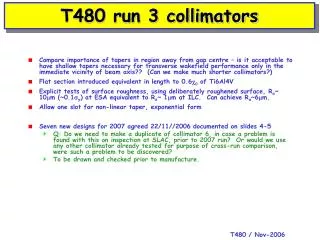
Set-up of single collimator BLM BLM BLM BLM BLM BLM Beam Beam Beam Beam Beam Shower Shower Shower Shower Calibrated center and width of gap, if beam extension is known (e.g. after scraping). Advance with experience! Rely on relative readings from BLM system... No demand on absolute understanding. BLM BLM BLM BLM BLM BLM
LHC Collimator Set Up Limitations • Collimator setup must be done with low intensity (hierarchy not respected during setup). Few nominal bunches at 7 TeV (~close to Tevatron stored energy). • Rely on reproducibility of the machine. Helped by only working with bunches of ONE intensity – only change number of bunches, not bunch intensity. • Good reproducibility and stability is crucial for the LHC! • Feedback from orbit measurements to collimator settings, if orbit is not stabilized as specified or not reproducible. • In parallel work on more advanced methods: • Understand changes from 450 GeV to 7 TeV adjust 7TeV collimator settings with 450GeV data? • Do 7 TeV collimator set-up on secondary halo or pattern of beam loss measurement? • Phase 2: buttons in jaws for deterministic setup of collimators (center around beam by equalizing pick up signal of two buttons, coupled to jaws). • Reproducibility is not evident. However, advanced methods challenging!
Principle for Collimator Set-up at 7 TeV Inject 5 nominal bunches Inject high intensity Inject high intensity Inject high intensity Collimator set up 450 GeV (1-4 batches) Collimator set up 450 GeV (1-4 batches) Collimator set up 450 GeV (1-4 batches) Bad Good Ramp Ramp Ramp Restore beam conditions and collimator settings Collimator set up at 7 TeV (build on Tevatron scheme) Restore beam conditions and collimator settings NO NO Record beam parameters and collimator settings Good? Good? YES YES Physics Physics Beam Dump Beam Dump Beam Dump
Definition of “Good” and “Bad” • Collimation efficiency will be measured after every set-up. • Measurement method: • Generate diffusive beam losses in one plane (will always end up on primary collimator after collimator setup). Can be done with transverse feedback, tunes, kicker, … • Measure intensity loss rate (p/s). • Record beam loss monitor readings. • Increase diffusion speed until the target loss rate (efficiency) is reached. • For example with phase 1 we should reach 1 × 10¹¹ p/s (conclusion: efficiency OK). • Performance reach: Increase diffusion speed while recording intensity loss rate. Push up to quench or BLM generated abort.
Measured Cleaning Efficiency Known… Measure • Measure (dI/dt)max at the abort limit of the BLM or until we quench. • Deliverable of the collimation system: Target cleaning efficiency (support DC betatron beam losses of up to 1.6 × 10¹¹ p/s at 7 TeV – 200 kJ/s). • Once design has been reached, the collimation is commissioned. • Can be achieved, once full phase 1 is installed: 2009. Should be able to reach 0.8 × 10¹¹ p/s with 2008 system.
Outline • Introduction • Collimation in procedures • General strategy for safe commissioning and operation • Beam based collimator calibration • Commissioning Preparations: Settings, Ramp, Orbit, Squeeze • Conclusion
Commissioning Preparations: 7 TeV Settings for Various Intensities
Commissioning Preparations: Efficiency and Quench Limit During the Ramp C. Bracco QL 450 GeV QL 7 TeV Two observations: 1) Quench limits go down. 2) Local losses in DS go up because collimator not closed!
Commissioning Preparations: Triplet Aperture During Squeeze Beam 1, right Beam 1, left T. Weiler Beam 2, right Beam 2, left
Commissioning Preparations: Collimation During the Squeeze Adjust coll IR3/7 for n1 of next b* step (apply 1 s margin) End of Ramp Measure tail population to 6 s LOW Correct machine HIGH Scraping of tails Verify coll settings Adjust dump protec-tion (TCDQ+TCS) Set absorbers for physics debris (TCLP) Switch off FB (transv) Adjust triplet collimators (TCT) Switch on octupoles Put beams into collision Correct machine Squeeze each IR to next b* step (maybe track TCT’s with crossing bumps) Check feedbacks Switch off octupoles? Squeeze to b*=6 m all relevant IR’s Correct machine Correct machine Check losses and background End of squeeze? Correct machine YES NO Physics
Commissioning Preparations: Collimation During the Squeeze (Low Intensity) Adjust coll IR3/7 for n1 of next b* step (apply 1 s margin) End of Ramp Measure tail population to 6 s LOW Correct machine HIGH Scraping of tails Verify coll settings Adjust dump protec-tion (TCDQ+TCS) Switch off FB (transv) Adjust triplet collimators (TCT) Put beams into collision Correct machine Squeeze each IR to next b* step (maybe track TCT’s with crossing bumps) Check feedbacks? Correct machine Check losses and background Squeeze to b*=6 m all relevant IR’s Correct machine End of squeeze? Correct machine Physics YES NO
Commissioning Preparations:Squeeze Routine Operation Procedure End of Ramp Automated squeeze, crossing changes and collimator closing (function-driven) Correct machine Automated scraping Verify coll settings Set absorbers for physics debris (TCLP) Switch off FB (transv) Correct machine Switch on octupoles Put beams into collision Correct machine Switch off octupoles Correct machine Check losses and background Physics
5) Conclusion • Thorough hardware commissioning and cold checkout is establishing known collimators with safe position monitoring (talk O. Aberle). • Collimator commissioning included into commissioning procedures. • A general strategy for safe commissioning and operation of the collimation system has been defined. Discussed possible share of work and responsibility. • A strong team has been trained for collimator commissioning. Try to learn as much as possible from Tevatron and RHIC. PhD on commissioning: May 2008. • Collimation set-up is necessarily different from Tevatron and very different from LEP (no ad-hoc tuning)! • Procedures have been worked out, based on detailed LHC simulations (number of collimators versus performance, ramp, squeeze, …) and tested in the SPS with an LHC prototype collimator. • Performance will be continuously improved (Tevatron: factor 2 per year over 6 years) for the LHC. All the tools in hand: waiting for beam…