Enhancing Collimator Designs: Key Considerations for Geometric Components and Taper Angles
70 likes | 189 Vues
This document discusses the critical aspects of developing new collimator designs, focusing on geometric and resistive components. Key questions include the optimal dimensions for tapered sections, the effectiveness of exponential tapers, and the achievable experimental resolution based on T-480 studies. We address constraints like the minimum wall thickness and taper angles, while considering the implications of design choices on system impedance and damage mitigation strategies. Ultimately, we seek to determine if additional simulations are warranted before proceeding to manufacturing stages.

Enhancing Collimator Designs: Key Considerations for Geometric Components and Taper Angles
E N D
Presentation Transcript
Run 3, thoughts about new collimators • What would we like to find out? • How to add geometric/resistive components? • How much large does tapered section need to be? • Are e.g. exponential tapers better? • …? • What do we have the experimental resolution to study? • From T-480 studies so far • Estimated resolution on fitted deflection/collimator offset in linear region = nnn mrad/mm • Predicted resolution = mrad/mm • Meaningless to try to compare designs which differ by less than nnn mrad/mm
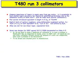
Importance of taper angle L a=50mrad a L Thickness = L sina e.g. for Ti6Al4V, 0.6c0 = 21.6mm 1.1mm • If we use ~ “hollowed out” design for damage mitigation, need to be careful with use of taper angles to reduce wakefields, cannot use ever smaller angles if 0.6c0 material distributed along taper … • Assume minimum realistic thickness of wall is 1mm • Constrains taper angle to min. 50mrad • Trailing edge also to consider, factor x2 – “thin” trailing edge of material in damage studies is actually same as our 0.6rad. length material budget! • Shorter jaws would make for cheaper overall system – can we achieve low impedance from fine tuning of geometry close to centre of beam pipe without using extremely small taper angles? • See e.g. some of Jonny’s GdfidL predictions for collims. 6-8 from 2006
38 mm 7 mm cf. collim. 4 smaller r h=38 mm cf. collim. 2, same r 211mm 31mm cf. collims. 4 and 6 133mm cf. collim. 7, and same step in/out earlier data Runs 1-2
38 mm h=38 mm 133mm As 8, unpolished EDM process, “hollowed” - exists 133mm As used in 2006, necessary for consistency Runs 3, 2007? 133mm As 9, in Ti-6Al-4V - exists 21mm cf. collim. 6, 13
38 mm 21 mm h=38 mm 21 mm 52 mm OFE Cu cf. collim. 7 – unpolished EDM Ti6Al4V = 0.6c0 Ti6Al4V cf. collims. 7, 13 – unpolished EDM Runs 3, 2007? 21 mm cf. collim. 13 125 mm OFE Cu 21 mm Form t.b.d. cf. ?
(Not) conclusions • Decisions needed ~ now • Do we need additional simulations before starting to manufacture? • Collim. 11 (a.k.a. George’s “F”) • Better than George “G”? • I think so, clearer to compare 11 with 13 than 11 with “G” • Explicit tests of surface roughness, using deliberated roughened surface, Ra~ 10mm (~0.1sy), same as EDM would be relative to real ILC sy • Only leaves room for one non-linear taper design – is this enough??