DSB-SC & SSB
DSB-SC & SSB. DSB-SC Modulation. A DSB-SC signal is an AM signal of the form: S(t)=Ac m(t) cosw c t Normal AM signal : S(t)=Ac[1+um(t)] cosw c t =Ac cosw c t +Ac u m(t) cosw c t. Frequency spectrum of DSB-SC signal.


DSB-SC & SSB
E N D
Presentation Transcript
DSB-SC Modulation • A DSB-SC signal is an AM signal of the form: S(t)=Ac m(t) coswct • Normal AM signal : S(t)=Ac[1+um(t)] coswct =Ac coswct +Ac u m(t) coswct
Frequency spectrum of DSB-SC signal • Let M(f) be the Fourier transform of m(t), then the fourier transform of the DSB-SC is: S(f)= Ac/2 M(f-fc)+Ac/2 M(f+fc) • Notes: • No impulses are present at ±fc; no carrier transmitted. • The transmission bandwidth is 2W (same as normal AM). • Power efficiency= (Power in the sideband/ total transmitted power) * 100% = 100%
SSB Modulation • Here only one of the two sidebands of a DSB-SC signal is retained while the other sideband is suppressed. • This means that the bandwidth requirement is half that for DSB-SC. • This saving in B.W comes at the expense of increasing modulation and demodulation complexity. • In SSB modulation we eliminate the carrier and one sideband, thus less transmitted power is needed, and approximately 83% power efficiency is achieved.
Generation of SSB Signal • A SSB signal can be generated either by: • Filtering Method. • Phase discrimination method. • Filtering Method: • The SSB signal is obtained by selecting either the upper- side band(USB) or the lower-Sideband (LSB) of the DSB-SCby means of a suitable band pass filter. • A band pass filter with appropriate BW and center frequency is used to pass the desired side band only.
Phase Discrimination method: • This method is based on the time representation of the SSB signal: S(t)=Acm(t)coswct ±Ac m*(t) sin wct (-) : upper side band is retained. m*(t): the hilbert transform of m(t).
Notes: • TP5 represents (DSB-SC)Q which is the quadrature component: (DSB-SC)Q = cos2π(fc-fm)t - cos2π(fc+fm)t • TP6 represents the (DSB SC)I which is the in phase componen: (DSB-SC)I = cos2π(fc-fm)t+ cos2π(fc+fm)t
To generate the SSB signal, an adder is used to obtain the desired side band: - Lower side-band: LSSB= (DSB-SC)I+ (DSB-SC)Q= 2cos2π(fc-fm)t - Upper side-bad: USSB= (DSB-SC)I- (DSB-SC)Q= 2cos2π(fc+fm)t
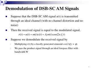
DSB-SC and SSB Demodulation • In this experiment , a coherent detector is used to recover the message signal. • S(t) is multiplied by a locally generated signal at the receive which has the same frequency and phase as c(t) at the transmitter, then it passes through a low-pass filter.
Example on DSB-SC Demodulation: • Consider s(t) represents a DSB-SC signal, after the multiplication process the signal will be: V(t)= s(t) Ac* coswct = Ac Ac*/2 m(t)+ Ac Ac*/2 m(t) cos 2wct • The high frequency term can be eliminated using a low pass filter.