Digital Electronic Signals and Switches
340 likes | 598 Vues
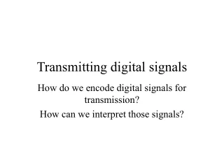
Objectives. You should be able to:Describe the parameters of digital-versus-time waveforms.Convert between frequency and period for a periodic waveform.Sketch the timing waveform for a binary string in either serial or parallel form.(Discuss the applications of mechanical switches and electrome

Digital Electronic Signals and Switches
E N D
Presentation Transcript
1. Chapter 2 Digital Electronic Signals and Switches
2. Objectives You should be able to:
Describe the parameters of digital-versus-time waveforms.
Convert between frequency and period for a periodic waveform.
Sketch the timing waveform for a binary string in either serial or parallel form.
(Discuss the applications of mechanical switches and electromechanical relays in electric circuits.)
3. Objectives (Continued)
Explain the characteristics of diodes and transistors when forward and reverse biased.
Calculate output voltage in circuits containing diodes or transistors used as digital switches.
Perform I/O timing analysis in circuits containing relays or transistors.
Explain the operation of a common-emitter transistor circuit used as a digital inverter.
4. Digital Signals Timing diagram
Voltage is measured on the y-axis; time on the x-axis
0 and 1 correspond to 0 V and 5 V
Can be viewed using an oscilloscope.
5. Clock Waveform Timing Periodic waveform
Repetitive
Specific time interval
Successive pulses are identical
Period � the time from one edge to the corresponding edge on the next cycle
tp = 1/f
Frequency � reciprocal of waveform period
f = 1/tp
6. Engineering Notation
7. Discussion Points What does the vertical scale of an oscilloscope represent?
What does the horizontal scale of an oscilloscope represent?
Describe frequency and period.
What is the period of a 75 MHz waveform?
What is the frequency of a waveform with a period of 20 ns?
8. Serial Representation
9. Serial Representation Single electrical conductor
Slow
One bit for each clock period
Telephone lines, computer-to-computer
COM ports are most often used for serial communications
Plug-in cards
10. Serial Representation Standards
V.90, ISDN, T1, T2, T3, USB, Ethernet, 10baseT, 100baseT, cable, DSL
Standard COM port transmission rate: 115 kbps
USB � Different speeds, depending on version � typically in hundreds of Mbps.
11. Parallel Representation
12. Parallel Representation Separate electrical conductor for each bit
Expensive
Very fast
Inside a computer
Data bus
External Devices
Centronics printer interface (LPT1)
SCSI (Small Computer Systems Interface)
13. Parallel Representation LPT1
8-bit parallel
115 kBps
SCSI
16-bit parallel
Up to 160 MBps
Bps - bytes per second
14. Discussion Points Describe the difference between parallel and serial transmission.
What advantage does parallel transmission have over serial transmission?
Are there any disadvantages to parallel transmission?
How long will it take to transmit two 8 bit binary strings using both serial and parallel if the clock frequency is 25 MHz?
15. Switches in Electronic Circuits Make or break connections between conductors
Manual switches
Electromechanical relays
Semiconductor devices
Diodes
Transistors
Manual Switches - ideal resistances:
ON - 0 W
OFF - ? ?
16. A Diode as a Switch Semiconductor
Current in one direction only
Forward-biased
Anode more positive than cathode
Current
Reverse-biased
Anode equal or more negative than cathode
No current
17. A Diode as a Switch Analogous to a water check valve
Not a perfect short
0.7 V across its terminals
18. A Transistor as a Switch Bipolar junction transistor (BJT)
Three-terminal component
An input signal at one terminal generates a short or open between the other two terminals
Terminals: base, emitter, and collector
Two types
NPN
PNP
19. A Transistor as a Switch NPN
Positive base-to-emitter voltage shorts the transistor output (collector-to-emitter)
Transistor is said to be ON
Negative voltage (or 0 V) base-to-emitter opens the transistor output (collector-to-emitter)
Transistor is said to be OFF
20. A Transistor as a Switch PNP
Negative base-to-emitter voltage shorts the transistor output (collector-to-emitter)
Transistor is said to be ON
Positive voltage (or 0 V) base-to-emitter opens the transistor output (collector-to-emitter)
Transistor is said to be OFF
21. Discussion Points Name the three pins (leads) of a transistor.
Describe how to turn an NPN transistor ON.
Describe how to turn a PNP transistor ON.
Example 2-11, 2-12
22. The TTL Integrated Circuit Transistor-Transistor Logic (TTL)
Inverter
The output is the complement of the input. (Converts 1 to 0 and vice-versa)
TTL Integrated Circuit
Totem-pole output
23. The TTL Integrated Circuit 7404 Hex Inverter
Six complete logic circuits on a single silicon chip
14 pins, 7 on a side
DIP (dual-in-line package)
Pin configuration
24. The CMOS Integrated Circuit Complementary Metal Oxide Semiconductor
Low power consumption
Useful in battery-powered devices
Slower switching speed than TTL
Sensitive to electrostatic discharge
NC = Not Connected
25. Surface-Mount Devices SMD
Reduced size and weight
Lowered cost of manufacturing circuit boards
Soldered directly to metal footprint
Special desoldering tools and techniques
Chip densities increased
Higher frequencies
26. Surface-Mounted Devices SO (Small Outline)
Dual-in-line package; gull-wing format
Lower-complexity logic
PLCC (Plastic Leaded Chip Carrier)
Leads on all four sides; J-bend configuration
More complex logic
BGA (Ball Grid Array)
Higher pin counts than PLCC or SO
Connections made through round solder tabs on the bottom of the component.
27. Discussion Points What are some key characteristics of:
TTL devices
CMOS devices
Surface mount devices
From a technician�s standpoint, is there a problem troubleshooting and repairing SMD based equipment?
28. Summary The digital level for 1 is commonly represented by a voltage of 5 V in digital systems. A voltage of 0 V is used for the 0 level.
An oscilloscope can be used to observe the rapidly changing voltage-versus-time waveform in digital systems.
29. Summary The frequency of a clock waveform is equal to the reciprocal of the waveform�s speed
The transmission of binary data in the serial format requires only a single conductor with a ground reference. The parallel format requires several conductors but is much faster than serial.
30. Summary Electromechanical relays are capable of forming shorts and opens in circuits requiring high current values but not high speed.
Diodes are used in digital circuitry whenever there is a requirement for current to flow in one direction but not the other.
31. Summary The transistor is the basic building block of the modern digital integrated circuit. It can be switched on or off by applying the appropriate voltage at its base connection.
TTL and CMOS integrated circuits are formed by integrating thousands of transistors in a single package. They are the most popular ICs used in digital circuitry today.
32. Summary SMD-style ICs are gaining popularity over the through-hole style DIP ICs because of their smaller size and reduced manufacturing costs.
33. Review Questions P31
P35
P42
P46
P53