Download
1 / 11
110 likes | 246 Vues
This guide delves into the fundamentals of digital signals and switches, crucial components in computer organization and digital electronics. It explains how to assign logical values to voltages, the significance of timing diagrams, and the relationship between frequency and period. The document covers various types of switches, including ideal, manual, and automatic (e.g., relays, transistors), while also illustrating their behavior with voltage signals. By understanding these concepts, you'll gain insight into how logic levels change in digital circuits and the principles of signal processing.

E N D
Digital Signals and Switches Cosc 235: Computer Organization and Digital Electronics
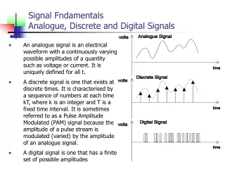
voltage time Digital signals • Logically assign “high” or “1” to a voltage above a certain threshold • Logically assign a “low” or “0” to a voltage below a certain threshold • Timing diagram • Change of voltage plotted vs. time Sample clock signal
Clock waveform timing • Period tp Length of time from the falling edge of one pulse to the falling edge of the next (or rising edge to rising edge) Unit: seconds • Frequency f How many cycles we have per second Unit: Hertz (cycles per second) • Note f = 1/tp and tp = 1/f
Example What is the frequency of a clock waveform whose period is 10 s? f = 1/tp = 1/10 s = 100,000 Hz
Switches Change in logic levels is due to switching between voltage levels • Ideal • Manual • Electromechanical relay • Diode • Transistor
Ideal switch • Automatic • Instantaneous • R = 0 when switch is closed • R when switch is open • Uses no power (Unrealizable)
Manual switch • Close to ideal, not automatic Signal Switch Output 0 0 (open) 0 0 1 0 1 0 0 1 1 1 Signal Switch Output AND function
A X 0 1 1 0 Switches • Automatic switch: relay • Open/Closing are controlled via an electromagnet and solenoid arrangement • Inverting switch X +5v A
A B X 0 0 0 0 1 0 1 0 0 1 1 1 Switches • Diode as a switch A +5v B A/B (inputs) high: +5v A/B (inputs) low: ground X
RC RL Transistor Switches: RTL inverter +5v A low (=ground): Is transistor on? Most current flows through where? A high: Is transistor on? Most current goes through where? X RB A RL >> RC, RB No RC & RL So X is High Yes Transistor So X is Low Other inputs (series/parallel)
Transistor switches: TTL logic +5v X RC T2 T1 Use T1 as 2 diodes RB +5v A High A low (gnd): T1down; T2off, so X is? A High (+5v): T1up; T2on, so X is? Low