Download
1 / 13
130 likes | 254 Vues
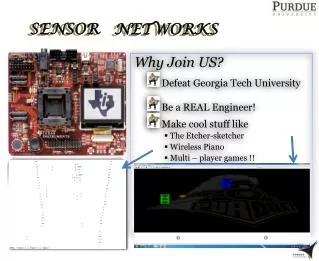
This senior design project focuses on developing an advanced racquetball court sensor system by Andy Lai and Kevin McCrory. The aim is to eliminate human judgment errors during games by providing precise ball detection in the lower front corner of the court without obstructing play. The system utilizes a LK11 laser pointer for accurate measurements, paired with a fast MRD 510 photo detector. Challenges include solving timing and feedback issues, optimizing circuitry, and addressing power supply constraints. Future improvements involve using sophisticated lasers and conducting extensive field tests.

E N D
Racquetball Court Sensor Andy Lai Kevin McCrory ECE 345 – Senior Design
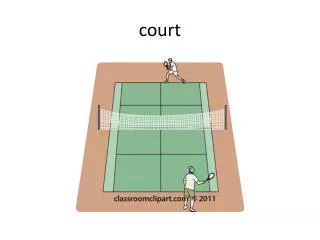
Project Purpose • Eliminate human error in judgement during a racquetball game • Provide accurate detection in the lower front corner of the court • Ensure the detection system does not obstruct play and court parameters
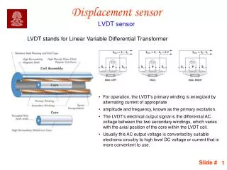
Emitters and Detectors • LK11 laser pointer emits a wavelength of 645 nm • Beam reaches up to 1500 ft • MRD 510 photo detector (flat lens) • < 1 ns response time • Amplification
Original Design Wall sensor Output to Device Op Amps D Flip Flops Gain of 10 Slow Clock Floor Sensor Fast Clock
Working Design 555 Timer D Q (( )) J Q D Q High input K Q CLR D Flip Flops Set and Clear are High Op Amps Gain of 10 D R Q PE H CET CEP 10 Hz clock 1 MHz Clock
Truth Tables J = 1 and K = 1 never exists. If exists, output will toggle.
Logic Issues • Holding the buzzer output • Original design did not correct the “wall problem” • Solution: Same as holding the buzzer output • Delay logic simplified with the 555 Timer • 555 Timer eliminates 3 logic components and solves the feedback problem in “wall problem”
Timing and Delay • Approximately 59.6 ns delay from wall sensor to J/K flip flop • Floor must be tripped at a time > 59.6 ns after the wall was tripped 59.6 ns Wall Sensor Floor Sensor Both tripped At J/K F/F
More Timing and Delay • Signal response time • Time = distance / rate • Time = .0127 m / 31.29m/s = .406 ms or 406000 ns • Satisfies detector response time
Testing • Built model racquetball floor • Plexiglass did not impede or diffract the transmission of the laser beam • For simplicity and convenience, two-input toggle switches were used to mimic the sensor during testing • On-going logic tests
Problems and Challenges • Delay logic • Feedback loop in the wall D flip-flop • Continuous D flip-flop failures • Laser pointer battery lifetime
Recommendations • Perform tests with full laser array • Optimize the sensor distance from the floor and the wall • Perform detailed analysis of TTL circuit to ensure functionality of devices • Shrink logic with PLDs or FPGAs for final product • Hardwire lasers to a voltage source to eliminate battery lifetime issue • Implement more sophisticated lasers • Actual field test