Download

1 / 27
300 likes | 522 Vues
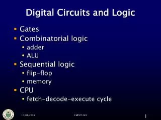
Introduction. DIGITAL LOGIC CIRCUITS. Logic Gates Boolean Algebra Map Specification Combinational Circuits Flip-Flops Sequential Circuits Memory Components Integrated Circuits. Logic Gates. LOGIC GATES. Digital Computers

E N D
Introduction DIGITAL LOGIC CIRCUITS Logic Gates Boolean Algebra Map Specification Combinational Circuits Flip-Flops Sequential Circuits Memory Components Integrated Circuits
Logic Gates LOGIC GATES Digital Computers - Imply that the computer deals with digital information, i.e., it deals with the information that is represented by binary digits - Why BINARY ? instead of Decimal or other number system ? * Consider electronic signal 1 7 6 5 4 3 2 1 0 signal range 0 binary octal 0 1 2 3 4 5 6 7 8 9 * Consider the calculation cost - Add 0 0 1 2 3 4 5 6 7 8 9 1 1 2 3 4 5 6 7 8 9 10 2 2 3 4 5 6 7 8 9 1011 3 3 4 5 6 7 8 9 101112 4 4 5 6 7 8 9 10111213 5 5 6 7 8 9 1011121314 6 6 7 8 9 101112131415 7 7 8 9 10111213141516 8 8 9 1011121314151617 9 9 101112131415161718 0 1 0 1 1 10 0 1
Logic Gates BASIC LOGIC BLOCK - GATE - Binary Digital Output Signal Binary Digital Input Signal Gate . . . Types of Basic Logic Blocks - Combinational Logic Block Logic Blocks whose output logic value depends only on the input logic values - Sequential Logic Block Logic Blocks whose output logic value depends on the input values and the state (stored information) of the blocks Functions of Gates can be described by - Truth Table - Boolean Function - Karnaugh Map
Logic Gates COMBINATIONAL GATES Name Symbol Function Truth Table A B X A X = A • B X or B X = AB 0 0 0 0 1 0 1 0 0 1 1 1 0 0 0 0 1 1 1 0 1 1 1 1 AND A B X A X X = A + B B OR A X I 0 1 1 0 A X X = A A X 0 0 1 1 Buffer A X X = A A B X A X X = (AB)’ B 0 0 1 0 1 1 1 0 1 1 1 0 NAND A B X A X X = (A + B)’ B 0 0 1 0 1 0 1 0 0 1 1 0 NOR A B X A X = A B X or B X = A’B + AB’ XOR Exclusive OR 0 0 0 0 1 1 1 0 1 1 1 0 A B X A X = (A B)’ X or B X = A’B’+ AB XNOR 0 0 1 0 1 0 1 0 0 1 1 1 Exclusive NOR or Equivalence
Boolean Algebra BOOLEAN ALGEBRA Boolean Algebra * Algebra with Binary(Boolean) Variable and Logic Operations * Boolean Algebra is useful in Analysis and Synthesis of Digital Logic Circuits - Input and Output signals can be represented by Boolean Variables, and - Function of the Digital Logic Circuits can be represented by Logic Operations, i.e., Boolean Function(s) - From a Boolean function, a logic diagram can be constructed using AND, OR, and I Truth Table * The most elementary specification of the function of a Digital Logic Circuit is the Truth Table - Table that describes the Output Values for all the combinations of the Input Values, called MINTERMS - n input variables --> 2n minterms
Boolean Algebra LOGIC CIRCUIT DESIGN x y z F 0 0 0 0 0 0 1 1 0 1 0 0 0 1 1 0 1 0 0 1 1 0 1 1 1 1 0 1 1 1 1 1 Truth Table Boolean Function F = x + y’z x F y Logic Diagram z
Boolean Algebra BASIC IDENTITIES OF BOOLEAN ALGEBRA [1] x + 0 = x [3] x + 1 = 1 [5] x + x = x [7] x + x’ = 1 [9] x + y = y + x [11] x + (y + z) = (x + y) + z [13] x(y + z) = xy +xz [15] (x + y)’ = x’y’ [17] (x’)’ = x [2] x • 0 = 0 [4] x • 1 = x [6] x • x = x [8] x • X’ = 0 [10] xy = yx [12] x(yz) = (xy)z [14] x + yz = (x + y)(x + z) [16] (xy)’ = x’ + y’ Usefulness of this Table - Simplification of the Boolean function - Derivation of equivalent Boolean functions to obtain logic diagrams utilizing different logic gates -- Ordinarily ANDs, ORs, and Inverters -- But a certain different form of Boolean function may be convenient to obtain circuits with NANDs or NORs --> Applications of DeMorgans Theorem x’y’ = (x + y)’ x’+ y’= (xy)’ I, AND --> NOR I, OR --> NAND [15] and [16] : De Morgan’s Theorem
Boolean Algebra EQUIVALENT CIRCUITS Many different logic diagrams are possible for a given Function F = ABC + ABC’ + A’C .......…… (1) = AB(C + C’) + A’C [13] ..…. (2) = AB • 1 + A’C [7] = AB + A’C [4] ...…. (3) A B C (1) (2) (3) F A B C F A B C F
Boolean Algebra COMPLEMENT OF FUNCTIONS A Boolean function of a digital logic circuit is represented by only using logical variables and AND, OR, and Invert operators. --> Complement of a Boolean function - Replace all the variables and subexpressions in the parentheses appearing in the function expression with their respective complements A,B,...,Z,a,b,...,z A’,B’,...,Z’,a’,b’,...,z’ (p + q) (p + q)’ - Replace all the operators with their respective complementary operators AND OR OR AND - Basically, extensive applications of the DeMorgan’s theorem (x1 + x2 + ... + xn )’ x1’x2’... xn’ (x1x2 ... xn)' x1' + x2' +...+ xn'
Map Simplification SIMPLIFICATION Boolean Function Truth Table Many different expressions exist Unique Simplification from Boolean function - Finding an equivalent expression that is least expensive to implement - For a simple function, it is possible to obtain a simple expression for low cost implementation - But, with complex functions, it is a very difficult task Karnaugh Map(K-map) is a simple procedure for simplifying Boolean expressions. Truth Table Simplified Boolean Function Karnaugh Map Boolean function
Map Simplification KARNAUGH MAP Karnaugh Map for an n-input digital logic circuit (n-variable sum-of-products form of Boolean Function, or Truth Table) is - Rectangle divided into 2n cells - Each cell is associated with a Minterm - An output(function) value for each input value associated with a mintern is written in the cell representing the minterm --> 1-cell, 0-cell Each Minterm is identified by a decimal number whose binary representation is identical to the binary interpretation of the input values of the minterm. Karnaugh Map x 0 value of F x 0 Identification of the cell 0 x F 0 1 1 0 0 1 1 1 1 (1) F(x) = 1-cell y 0 1 y x y F 0 0 0 0 1 1 1 0 1 1 1 1 x 0 1 0 1 2 3 x 0 0 0 1 1 1 0 1 F(x,y) = (1,2)
Map Simplification KARNAUGH MAP x y z F y 0 0 0 0 0 0 1 1 0 1 0 1 0 1 1 0 1 0 0 1 1 0 1 0 1 1 0 0 1 1 1 0 yz yz 00 01 11 10 00 01 11 10 x x 0 0 0 1 0 1 0 1 3 2 4 5 7 6 x 1 1 0 0 0 1 z F(x,y,z) = (1,2,4) w wx 00 01 11 10 u v w x F uv 0 0 0 0 0 0 0 0 1 1 0 0 1 0 0 0 0 1 1 1 0 1 0 0 0 0 1 0 1 0 0 1 1 0 1 0 1 1 1 0 1 0 0 0 1 1 0 0 1 1 1 0 1 0 0 1 0 1 1 1 1 1 0 0 0 1 1 0 1 0 1 1 1 0 1 1 1 1 1 0 0 1 3 2 00 v 01 4 5 7 6 11 12 13 15 14 u 10 8 9 11 10 x wx 00 01 11 10 uv 00 0 1 1 0 01 0 0 0 1 11 0 0 0 1 10 1 1 1 0 F(u,v,w,x) = (1,3,6,8,9,11,14)
Map Simplification MAP SIMPLIFICATION - 2 ADJACENT CELLS - Rule: xy’ +xy = x(y+y’) = x Adjacent cells - binary identifications are different in one bit --> minterms associated with the adjacent cells have one variable complemented each other Cells (1,0) and (1,1) are adjacent Minterms for (1,0) and (1,1) are x • y’ --> x=1, y=0 x • y --> x=1, y=1 F = xy’+ xy can be reduced to F = x From the map y 0 1 x 0 0 0 2 adjacent cells xy’ and xy --> merge them to a larger cell x 1 1 1 (2,3) F(x,y) = = xy’+ xy = x
Map Simplification u’v’ wx wx u’x’ w w uv uv 1 1 1 1 1 1 1 1 vw’ 1 1 1 1 v v 1 1 1 1 u u 1 1 1 1 uw x x v’x wx w w V’ uv uv 1 1 1 1 1 1 w’ 1 1 v v 1 1 1 1 1 1 u u u 1 1 1 1 1 1 x x MAP SIMPLIFICATION - MORE THAN 2 CELLS - u’v’w’x’ + u’v’w’x + u’v’wx + u’v’wx’ = u’v’w’(x’+x) + u’v’w(x+x’) = u’v’w’ + u’v’w = u’v’(w’+w) = u’v’ u’v’w’x’+u’v’w’x+u’vw’x’+u’vw’x+uvw’x’+uvw’x+uv’w’x’+uv’w’x = u’v’w’(x’+x) + u’vw’(x’+x) + uvw’(x’+x) + uv’w’(x’+x) = u’(v’+v)w’ + u(v’+v)w’ = (u’+u)w’ = w’
Map Simplification MAP SIMPLIFICATION wx 00 01 11 10 w uv 1 00 1 1 0 1 0 1 1 01 0 0 0 0 0 0 0 0 v 11 0 1 1 0 0 1 1 0 u 10 0 1 0 0 0 0 0 1 x F(u,v,w,x) = (0,1,2,9,13,15) (0,1), (0,2), (0,4), (0,8) Adjacent Cells of 1 Adjacent Cells of 0 (1,0), (1,3), (1,5), (1,9) ... ... Adjacent Cells of 15 (15,7), (15,11), (15,13), (15,14) Merge (0,1) and (0,2) --> u’v’w’ + u’v’x’ Merge (1,9) --> v’w’x Merge (9,13) --> uw’x Merge (13,15) --> uvx F = u’v’w’ + u’v’x’ + v’w’x + uw’x + uvx But (9,13) is covered by (1,9) and (13,15) F = u’v’w’ + u’v’x’ + v’w’x + uvx
Map Simplification x’ y’ x z’ x’ z F F y z’ y x z y z’ I AND OR IMPLEMENTATION OF K-MAPS- Sum-of-Products Form - Logic function represented by a Karnaugh map can be implemented in the form of I-AND-OR A cell or a collection of the adjacent 1-cells can be realized by an AND gate, with some inversion of the input variables. y x’ y 1 1 x’ z’ y’ x’ x 1 y z’ x 1 1 z’ z’ y z z’ 1 F(x,y,z) = (0,2,6)
Map Simplification IMPLEMENTATION OF K-MAPS- Product-of-Sums Form - Logic function represented by a Karnaugh map can be implemented in the form of I-OR-AND If we implement a Karnaugh map using 0-cells, the complement of F, i.e., F’, can be obtained. Thus, by complementing F’ using DeMorgan’s theorem F can be obtained F(x,y,z) = (0,2,6) y F’ = xy’ + z F = (xy’)z’ = (x’ + y)z’ z 1 1 0 0 x 0 0 0 1 x z y’ x y F z I OR AND
Map Simplification IMPLEMENTATION OF K-MAPS- Don’t-Care Conditions - In some logic circuits, the output responses for some input conditions are don’t care whether they are 1 or 0. In K-maps, don’t-care conditions are represented by d’s in the corresponding cells. Don’t-care conditions are useful in minimizing the logic functions using K-map. - Can be considered either 1 or 0 - Thus increases the chances of merging cells into the larger cells --> Reduce the number of variables in the product terms y x’ 1 d d 1 d 1 x yz’ z x F y z
Combinational Logic Circuits x y c s 0 0 0 0 0 1 0 1 1 0 0 1 1 1 1 0 x y c s COMBINATIONAL LOGIC CIRCUITS y y Half Adder 0 0 0 1 1 1 0 x 0 x c = xy s = xy’ + x’y = x y Full Adder y y x y cn-1 cn s 0 1 0 0 0 0 0 0 0 0 0 1 0 1 0 1 0 0 1 0 1 1 1 0 1 0 0 0 1 1 0 1 1 0 1 1 0 1 0 1 1 1 1 1 1 0 0 1 cn-1 cn-1 0 1 1 1 x x 0 0 1 1 cn s cn = xy + xcn-1+ ycn-1 = xy + (x y)cn-1 s = x’y’cn-1+x’yc’n-1+xy’c’n-1+xycn-1 = x y cn-1 = (x y) cn-1 x y S cn cn-1
Combinational Logic Circuits COMBINATIONAL LOGIC CIRCUITS Other Combinational Circuits Multiplexer Encoder Decoder Parity Checker Parity Generator etc
Combinational Logic Circuits Select Output S1 S0 Y 0 0 I0 0 1 I1 1 0 I2 1 1 I3 MULTIPLEXER 4-to-1 Multiplexer I0 I1 Y I2 I3 S0 S1
Combinational Logic Circuits D1 A0 D2 A1 D3 D4 D5 A2 D6 E A1 A0 D0 D1 D2 D3 D7 0 0 0 0 1 1 1 0 0 1 1 0 1 1 0 1 0 1 1 0 1 0 1 1 1 1 1 0 1 d d 1 1 1 1 ENCODER/DECODER Octal-to-Binary Encoder 2-to-4 Decoder D0 D1 A0 D2 D3 A1 E
Sequential Circuits SEQUENTIAL CIRCUITS - Registers A0 A1 A2 A3 Q Q Q Q C C C C D D D D Clock I0 I1 I2 I3 Shift Registers Serial Output Serial Input Clock D Q C D Q C D Q C D Q C Bidirectional Shift Register with Parallel Load A3 A1 A0 A2 Q Q Q Q C C C C D D D D 4 x 1 MUX 4 x 1 MUX 4 x 1 MUX 4 x 1 MUX Serial Input I3 I0 Clock S0S1 I1 I2 SeriaI Input
Memory Components n data input lines k address lines Read Write 2k Words (n bits/word) n data output lines MEMORY COMPONENTS 0 Logical Organization words (byte, or n bytes) N - 1 Random Access Memory - Each word has a unique address - Access to a word requires the same time independent of the location of the word - Organization
Memory Components k address input lines m x n ROM (m=2k) n data output lines READ ONLY MEMORY(ROM) Characteristics - Perform read operation only, write operation is not possible - Information stored in a ROM is made permanent during production, and cannot be changed - Organization Information on the data output line depends only on the information on the address input lines. --> Combinational Logic Circuit addressOutput ABC X0 X1 X2 X3 X4 X0=A’B’ + B’C X1=A’B’C + A’BC’ X2=BC + AB’C’ X3=A’BC’ + AB’ X4=AB X0=A’B’C’ + A’B’C + AB’C X1=A’B’C + A’BC’ X2=A’BC + AB’C’ + ABC X3=A’BC’ + AB’C’ + AB’C X4=ABC’ + ABC 000 001 010 011 100 101 110 111 1 0 0 0 0 1 1 0 0 0 0 1 0 1 0 0 0 1 0 0 0 0 1 1 0 1 0 0 1 0 0 0 0 0 1 0 0 1 0 1 Canonical minterms
Memory Components TYPES OF ROM ROM - Store information (function) during production - Mask is used in the production process - Unalterable - Low cost for large quantity production --> used in the final products PROM (Programmable ROM) - Store info electrically using PROM programmer at the user’s site - Unalterable - Higher cost than ROM -> used in the system development phase -> Can be used in small quantity system EPROM (Erasable PROM) - Store info electrically using PROM programmer at the user’s site - Stored info is erasable (alterable) using UV light (electrically in some devices) and rewriteable - Higher cost than PROM but reusable --> used in the system development phase. Not used in the system production due to erasability
Memory Components INTEGRATED CIRCUITS Classification by the Circuit Density SSI - several (less than 10) independent gates MSI - 10 to 200 gates; Perform elementary digital functions; Decoder, adder, register, parity checker, etc LSI - 200 to few thousand gates; Digital subsystem Processor, memory, etc VLSI - Thousands of gates; Digital system Microprocessor, memory module Classification by Technology TTL - Transistor-Transistor Logic Bipolar transistors NAND ECL - Emitter-coupled Logic Bipolar transistor NOR MOS - Metal-Oxide Semiconductor Unipolar transistor High density CMOS - Complementary MOS Low power consumption