EGN 1007 -Introduction to Aeronautical Engineering
210 likes | 458 Vues
EGN 1007 -Introduction to Aeronautical Engineering. Part II - Aircraft Controls. The 3 axes of movement. Unlike a car, which moves in 2 dimensions (left or right), a airplane can move in 3 dimensions. Lateral Axis (the “ pitch ”) Longitudinal Axis ( the “ roll ”) Vertical axis (the “ yaw ”).

EGN 1007 -Introduction to Aeronautical Engineering
E N D
Presentation Transcript
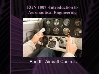
EGN 1007 -Introduction to Aeronautical Engineering Part II - Aircraft Controls
The 3 axes of movement Unlike a car, which moves in 2 dimensions (left or right), a airplane can move in 3 dimensions • Lateral Axis (the “pitch”) • Longitudinal Axis ( the “roll”) • Vertical axis (the “yaw”)
Ailerons and the “ROLL” A yoke or control wheel is a device used for piloting in most fixed-wing aircraft, analogous to a steering wheel in an automobile. Moving B left or right controls the roll by moving A up and down
Elevators and the “PITCH” By moving B (yoke or control stick) backwards or forwards a pilot can move part C, the ELEVATORS, up or down.
Rudders and the “YAW” Foot pressure on the left rudder pedal moves the rudder to the left, causing the nose of the airplane to move to the left. The opposite is true when using the right rudder pedal.
Using BOTH the rudder and ailerons : “SLIP/SKID” A slip is an aerodynamic state where an aircraft is moving sideways as well as forward relative to the oncoming airflow. Flying in a slip is aerodynamically inefficient and can also cause motion sickness in passengers. however there are common situations where a pilot may enter a slip deliberately by using opposite rudder and aileron inputs, most commonly in a landing approach at low power.
Basic Aircraft Instruments Six basic instruments in a light twin-engine airplane arranged in the basic-T. From top left:airspeed indicator, attitude indicator, altimeter, turn coordinator, heading indicator, and vertical speed indicator
Airspeed indicator Shows the aircraft's speed (usually in knots) relative to the surrounding air. It works by measuring the ram-air pressure in the aircraft's pitot tube (slide 14). The indicated airspeed must be corrected for air density (which varies with altitude, temperature and humidity) in order to obtain the true airspeed, and for wind conditions in order to obtain the speed over the ground.
Attitude indicator Shows the aircraft's attitude relative to the horizon. From this the pilot can tell whether the wings are level and if the aircraft nose is pointing above or below the horizon. This is a primary instrument for instrument flight ( slide 13) and is also useful in conditions of poor visibility. Pilots are trained to use other instruments in combination should this instrument or its power fail.
Altimeter Gives the aircraft's height (usually in feet or meters) above some reference level (usually sea-level) by measuring the local air pressure. It is adjustable for local barometric pressure (referenced to sea level) which must be set correctly to obtain accurate altitude readings.
Turn coordinator The turn coordinator is an aircraft instrument which displays to a pilot information about the rate of turn, rate of roll, and the 'quality' or 'coordination' of the turn. The quality of turn is indicated by an inclinometer. This is a glass tube mounted on the face of the instrument, below the symbolic airplane.
Heading indicator The heading indicator (Directional Gyro or DG) is an instrument used in an aircraft to inform the pilot of his heading. The primary means of establishing heading in most small aircraft is the magnetic compass, but that suffers from errors created by the 'dip' or downward slope of the earth's magnetic field. To remedy this, the pilot will typically maneuver the airplane with reference to the heading indicator, as the gyroscopic heading indicator is unaffected by dip and acceleration errors.
Vertical speed indicator Also sometimes called a variometer. Senses changing air pressure and displays that information to the pilot as a rate of climb or descent, usually in feet per minute or meters per second.
Instrument (IFR) vs. Visual (VFR) Instrument flight rules (IFR) are a set of regulations and procedures for flying aircraft whereby navigation and obstacle clearance is maintained with reference to aircraft instruments only. IFR is an alternative to visual flight rules (VFR), where the pilot is ultimately responsible for navigation, obstacle clearance and traffic separation using the see-and-avoid concept.
Pitot tube A Pitottube is a pressure measuring instrument used to measure fluid flow velocity, and more specifically, used to determine the airspeed of an aircraft.
Takeoff There are several types of takeoffs: • Regular Field – Using the normal runway length • Short Field – Using very little runway in the case there may be a possible obstacle • Soft Field – When there is a chance you may get stuck (mud)
Landings (Crab, De-Crab, Side Slip) De-Crab The objective of this technique is to maintain wings level and the aircraft position near the runway centerline during approach. The nose points into the wind so that the aircraft approaches the runway slightly skewed with respect to the runway centerline (crabbing).
Landings (Crab, De-Crab, Side Slip) Crab This is similar to the De-Crab technique. The principal difference is the aircraft touches down whilst still crabbing. The position on the runway is corrected after touch down. This applies significant slip angle to the tires, and increases the lateral loads on the undercarriage, so this technique is bounded by speed restrictions and is not generally recommended.
Landings (Crab, De-Crab, Side Slip) This requires a higher level of skill. The purpose of this technique is to maintain heading aligned with the centerline The initial phase of the approach is flown using the Crab technique to correct for drift. With a slight residual bank angle, a touchdown is typically accomplished, for the cross wind direction shown, with the right main wheels touching down just before the left wheels.