Download
1 / 13
130 likes | 264 Vues
Calibration, Installation & Commissioning of Sensors for the Alignment of Muon Endcap Chambers in the CMS Experiment. S. GURAGAIN , M. HOHLMANN Dept. of Physics, Florida Institute of Technology, Melbourne, FL 32901 . An Overview. Introduction of the system

E N D
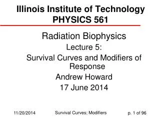
Calibration, Installation & Commissioning of Sensors for the Alignment of Muon Endcap Chambers in the CMS Experiment S. GURAGAIN, M. HOHLMANN Dept. of Physics, Florida Institute of Technology, Melbourne, FL 32901 SESAPS 2006 Samir Guragain
An Overview • Introduction of the system • Sensor calibration method and result • First commissioning results • Summary & conclusion SESAPS 2006 Samir Guragain
CMS Detector of LHC @CERN -Z Magnetic field 4 Tesla The CMS solenoid 13 m long with an inner diameter of 6 m Total weight 12500 t The largest superconducting solenoid ever made Overall diameter 15 m 3 Endcap disks and 4 layers on each side. Overall length 21.6 m SESAPS 2006 Samir Guragain
ME Alignment System Transfer plate Transfer plate Z-sensors Clinometers Note: only small sample of analog sensors shown R-sensors DCOPS The system monitors the positions of Cathode Strip Chambers relative to each other and to the MABs. The alignment uncertainty should be comparable to the chamber resolution and it is defined as 75 mm for ME1/2 and 150mm for the others stations. SESAPS 2006 Samir Guragain
Calibration method & result Linear mover Proximity sensor Prec. dowel pins Typical Z sensor Response (ME1) Sensor Response (V) Results Sensor response vs distance & Ratio of sensor response to ref. Volt vs distance are linear. Precision Reference Bar Slope = 1.0062 V/cm Error in slope = 0.00039 V/cm Acceptable Error Distance (cm) SESAPS 2006 Samir Guragain
Installation & Commissioning at CERN Cross hair Laser adjustment to pass it through four CCDs in each DCOPS on Straight Line Monitor (SLM) SESAPS 2006 Samir Guragain
First commissioning results • In summer 2006, all the sensors and readout were installed and commissioned on four positive endcap layers. • The detector was closed up and the huge 4 T solenoid magnet of CMS was turned on for the first time ever in Aug-Sep, 2006. • Data during the magnet test phase I & II were logged successfully at different B-field plateaus and have been analyzed. SESAPS 2006 Samir Guragain
P2 P3 P1 P4 P6 P5 Z sensor data analysis & Results on axial chamber displacement 6 laser displacement sensors were mounted on theYE+1 disk but only 3 MABs on YB+2. Displacement (mm) Finite element analysis predicts a distortion in Z-direction of endcap disks (outer edges) for about 6 mm that is in good agreement with Z1 laser displacement sensor data for upper point 2 but for lower point 5 and 6 the disk bend deformations are less than predicted. Quadratic dependence with magnetic field was observed B(T) Z Z1 SESAPS 2006 Samir Guragain
R sensor data analysis & Results on Radial displacement P2 Wire extension potentiometer P3 P1 R3 R2 P4 P6 P5 • At 4.0 T: • The largest displacement between chambers (ME+1 station) does not exceed ~ 700 mm • Chamber displacement relative to transfer • plates at outer edge is small (100-150 mm) Displacements between inner/outer chambers: ME+1: neg. sign => disk face compressed ME+2: pos. sign => disk face expanded ME+3: neg. sign => disk face compressed SESAPS 2006 Samir Guragain
Bending angle for ME+1-4 stations at outer edge Magnetic field = 4.0T 4 inner points Station +1 Station +2 2 Station +3 outer edge 0 Station +4 Tilt angle, mrad Average -2 Theory -4 0 1 2 3 4 5 6 7 Point # Inclinometer data analysis & Results on tilt angle displacement Disk Deformation: The current under- standing of yoke disk deformations due to magnetic forces based on these clinometer measurements Z-stop Capacitive fluid level monitor The bending angle for station ME+1 is larger closer to the center (~ 4 mrad) than at the outer edge of the ME+1 disk (~2.5 mrad). SESAPS 2006 Samir Guragain Z-stop
B (T) PX sensor data analysis & Results on azimuthal displacement Proximity sensors Azimuthal displacements vs. B: Proximity Sensors monitor the distances between the outer ring of muon chambers on station 1. This is the only ring where chambers do not overlap and tracks cannot be used to interpolate between SLMs. Distances between these chambers increased with magnetic field and reached up to 700 mm at 4.0T. SESAPS 2006 Samir Guragain
DCOPS beam profile Digital linear CCD-based Optical Position Sensor (DCOPS) with 4×1-d CCDs CCD 4 CCD 2 • 2048 pixels per CCD • 14 μm pixel pitch SESAPS 2006 Samir Guragain • 2048 pixels • per CCD • 14 μm pixel pitch
Summary & conclusion • About 400 analog sensors were calibrated precisely at Florida Tech and shipped to CERN for the installation. • The performance of the sensors up to 4T solenoid magnet during the test was good and they clearly indicated the flexing of the large absorber disks.The results are in good agreement with the finite element analysis predictions. • Now half of the system is ready to go into the underground cavern for final position of the detector. SESAPS 2006 Samir Guragain