Fingerprint recognition using MATLAB (using minutiae matching) Graduation project
670 likes | 1.29k Vues
Fingerprint recognition using MATLAB (using minutiae matching) Graduation project. Prepared by: Zain S. Barham Supervised by: Dr. Allam Mousa. Contents. Introduction Biometrics and fingerprint as recognition technique Algorithm System and algorithm design The process

Fingerprint recognition using MATLAB (using minutiae matching) Graduation project
E N D
Presentation Transcript
Fingerprint recognition using MATLAB (using minutiae matching)Graduation project Prepared by: Zain S. Barham Supervised by: Dr. Allam Mousa
Contents • Introduction Biometrics and fingerprint as recognition technique • Algorithm System and algorithm design The process • Evaluation and applications • Simulation
Introduction • Personal identification is to associate a particular individual with an identity • To ensure the services are accessed by a legitimate user • Traditional methods could be compromised • Lack of security
What are biometrics? • We all have unique personal attributes • Biometrics are individual physiological characteristics • It’s basically pattern -recognition that makes a personal identification
Why biometrics? • Your password can be stolen, your face can’t! • More reliable than traditional • More secure • Saves time
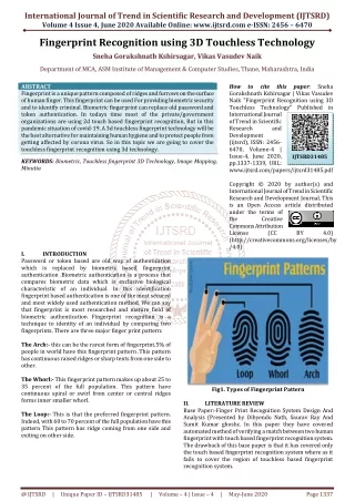
Fingerprints as biometrics • The major features in a print are called minutiae • Basic minutiae: ending & bifurcation
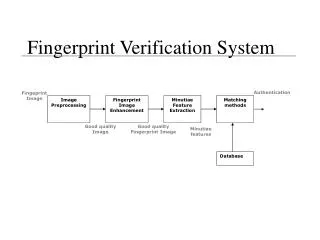
System level design Algorithm design System design
System level design • System consists of:
Algorithm Level Design • Image Enhancement • Image Binarization • Image segmentation • Thinning • Minutiae Marking • Remove False Minutiae
Algorithm Level Design Minutiae matcher: • Specify reference minutiae • Image alignment • Minutiae match
Image Enhancement Image Binarization Image segmentation Pre-processing
Preprocessing/ Image enhancement • Most important stage of project • There are lots of different ways to filter an image • The project was originally going to use edge detection
But after analysis, it turns out that for an image that looks like this:
This means that: • The result is an image with the borders of the ridges highlighted • This would call for the use of an extra step to fill out the shapes • And that would increase the complexity of the code • And would consume more processing time
So, I tried histogram equalization • It means to do a contrast adjustment on the image’s histogram • The intensities can be better distributed on the histogram
Function of histogram equalization • For a grayscale image {x} • let ni be the number of occurrences of gray level i. Then the probability of an occurrence of a pixel of level i in the image is: • ‘L’ is total number of gray levels in the image • ‘n’ is total number of pixels in the image • ‘px(i)’ is the image's histogram for pixel value i
Follow up: histogram equalization • Also, the cumulative distribution function corresponding to px is: • The transform of the image is defined as: • The cdf of a pixel x represents the probability that a random pixel is less than or equal to x
Follow up: histogram equalization • After this process, the cdf of each pixel is normalized to [0,255] • cdfmin is the minimum value of the cumulative distribution function (in this case 1) • M × N is the image's number of pixels • L is the number of grey levels used (most cases L=256)
Example: histogram equalization • For a matrix with the following pixel values:
Follow up: Example • The histogram for this matrix (shown in table form) is:
Follow up: Example • The cdf of the matrix is:
Follow up: Example • The normalized cdf becomes:
Follow up: histogram equalization • Now, applying that on an image with the following histogram:
Follow up: histogram equalization • Would result in a histogram that looks like this:
This is good because… • It allows for areas of lower local contrast to gain a higher contrast • Brings out dim and dark features, but washes out bright stuff • Betters details in photographs that are over or under-exposed
Fast Fourier transform • The Fourier transform is done to find the frequency of the pixel • So the output would be an image in the frequency domain.
Follow up: Fast Fourier transform • The image is divided into blocks in order to enhance a specific block by its dominant frequencies • so, the process is to multiply the FFT of the block by its magnitude a set of times
Preprocessing/ Image binarization • This step is done to convert a 256-level image to a 2-level image • It’s done to differentiate image pixels from background • Because of variations in contrast, locally adaptive thresholding is used
Follow up: Image binarization • First, the image is divided into blocks (16x16) • The mean intensity value is calculated for each block Assume gray value of each pixel=g; if g > Mean(block gray value) , set g = 1; Otherwise g = 0
Preprocessing/ Image segmentation • Only a certain Region of Interest (ROI) is useful to be recognized for each fingerprint image • To extract the ROI, a two-step method is used; block direction estimation and ROI extraction
Follow up: Image segmentation • Block direction estimation Get gradient x (gx),gradient y (gy) Estimate the according to: • ROI extraction (Morphological Method) Close (shrink images and eliminate small cavities) Open (expands images and remove peaks introduced by background noise)
Feature extraction Image thinning Minutiae marking
Feature extraction/ Image thinning • To eliminate the redundant pixels of ridges till the ridges are just one pixel wide • Morphological approaches: bwmorph(binaryImage,'thin',Inf) • This process is done by turning pixels off according to these conditions: • If there is at least 1 switch from on to off among boundary pixels • Not all 8-neighborhood pixels are on • Not a center nor ending pixel
Follow up: Image thinning • Filter by other Morphological operations to remove some H breaks and isolated points • In this step, any single points (single-point ridges or single-point breaks) in a ridge are eliminated and considered processing noise • Done using imerode and imfill
Feature extraction/ Minutiae marking • The concept of Crossing Number (CN) is used • CN is calculated by investigating the 8-neighborhood of each central pixel pixel (p) in order to determine the count of crossover occurrences Bifurcation Termination
Follow up: Minutiae marking • For a 3x3 window: If p=1 and has only 1 one-value neighbor, then the central pixel is a ridge ending If p=1 and has exactly 3 one-value neighbors, then the central pixel is a ridge branch i.e. for a pixel P, if Cn(P) = = 1 it’s a ridge end and if Cn(P) = = 3 it’s a ridge bifurcation (Cn being the number of 1-valued neighboring pixels)
Post-processing • False minutiae removal
False minutiae removal • Needed to get rid of noise introduced to image in: Acquisition process (over or under inking) Preprocessing stage
Examples: False minutiae removal Two terminations at a ridge are too close Two disconnected terminations short distance
Follow up: False minutiae removal There are 7 cases of false minutiae (length of block=average inter-ridge distance) a spike piercing into a valley a spike falsely connects two ridges
Follow up: False minutiae removal two near bifurcations located in the same ridge two near endings just like previous but with extra ridge one short ridge three near endings
Minutiae match Alignment Matching
Minutiae match/ Alignment To match 2 prints, determine their reference minutiae (most similar pair/at 0.8 threshold) using similarity equation: S = mi=0xiXi/[mi=0xi2Xi2]^0.5 where (xi~xn) and (Xi~XN) are the set of minutia for each fingerprint image respectively m is minimal one of the n and N value (n & N are total number of minutiae in each print)
Follow up: Alignment • Now, the reference minutia is the origin point of the coordinate system, and the x & y coordinates are found using its orientation angle.
Follow up: Alignment All other minutiae are then aligned to the new coordinate system, and component of their vectors can be found using the transform matrix: and the new values of x & y become:
Minutiae match/ Matching • Adaptive matching is used, not all parameters are exactly same • Achieved by placing a bounding box around each template minutia • If the minutia to be matched is within the rectangle box and difference between them is very small, then the two minutiae are regarded as a matched minutia pair
Follow up: Match or Non-match? • The final match ratio is: Match Score = Num(Matched Minutia) Max(Num Of Minutia(image1,image2)) • The score ranges from 0 to 100 • If the score is larger than a pre-specified threshold, the two fingerprints are from the same finger.