Download
1 / 20
200 likes | 345 Vues
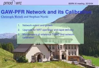
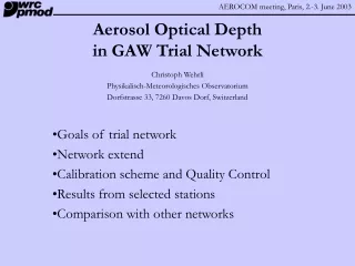
Aerosol Optical Depth with PFR instruments in GAW Trial Network. Christoph Wehrli Physikalisch-Meteorologisches Observatorium Dorfstrasse 33, 7260 Davos Dorf, Switzerland. Goals of trial network State of the network Calibration scheme Data processing approach

E N D
Aerosol Optical Depth with PFR instruments inGAW Trial Network Christoph Wehrli Physikalisch-Meteorologisches Observatorium Dorfstrasse 33, 7260 Davos Dorf, Switzerland Goals of trial network State of the network Calibration scheme Data processing approach Results from selected stations Comparison with other data
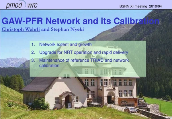
GAW/WORCC trial network Subsequent to the AOD fiasco in BAPMon, WORCC was proposed and established in 1996 at Davos, sponsored by Switzerland. Goals • Implement AOD measurements at 12 global observatories with new instrumentation, sound calibration, data quality control and protocols. • Test and verify new instruments and methods under operational network conditions. • Train station operators in AOD measurements. WORCC is assisted by a international group of experts and works in cooperation with GAW QA/SAC SAG/Aerosols assumes these roles. WMO initiated contacts between potential stations and WORCC for placement of instruments donated by MeteoSwiss. Host stations are to provide tracking facility and limited manpower.
State of trial network • Hohenpeissenberg, Germany, Jun.1999 • Mace Head, Ireland, Jul. 1999 • Boulder, USA, Aug. – Oct. 1999 Mauna Loa, Ha, USA, Nov. 1999 (Aeronet) • Bratt‘s Lake, Canada, Apr.2001 (BSRN, Aeronet) • Izaña, Spain, Jun. 2001 • Ryori, Japan, Jun. 2001 • Alice Springs, Australia, Jul. 2001 (BSRN) • Ny Ålesund, Norway, Apr. 2002 (BSRN) • Irkutsk, Russia • Bukit Koto Tobang, Indonesia • Brazil ? (Acre | Manaos) • Africa ? (Lamto) Jungfraujoch, Switzerland, Mar. since 1999 (CHARM) Davos, Switzerland, Nov. 1998 – Nov. 2000
Precision Filter Radiometer PFR specifications • Automated, solar spectral radiometer • 4 WMO channels at 862, 500, 412, 368nm using IAD interference filters • Field of View: ±2.5° , slope angle 0.7° • Dimensions: Ø90 x L300mm, Mass 3 kg • Sensor at 20±0.1°C in range –25 ÷ 35°C internal shutter; N2 purged, airtight housing • High cadence (2 or 1 min.) measurements • Data logger with 30 day storage capacity, built-in pressure and pointing sensors PFR N21 at Ryori, Japan.
WORCC Calibration Hierarchy • Standard instruments are calibrated at high altitude stations (Jungfraujoch, Mauna Loa) by atmospheric extrapolation methods. • Working standards are calibrated by com-parison with WORCC standards at Davos or Jungfraujoch. • Stability of standard instruments is moni-tored by spectral comparison with a metro-logically traceable absolute detector. • Station instruments are linked to WORCC reference by travelling standards or ex-change of sensors. • Performance is tested through intercom-parison of field instruments with other co-located networks.
Stratospheric Balloon Flight • Verification of Langley method by in situ measurements from SIMBA balloon flight in Oct.98 • PFR N01measurements at 40 km height. Atmospheric transmission corrected by MODTRAN calculation • PFR N02 mean of 19 refined Langley calibrations, obtained in Dec. 98 and Jan.99 at Jungfraujoch (3580m) • Comparison between N01 and N02 found agreement to < 1% • Langley calibration V0 are con-sistently higher than balloon.
High Altitude Calibration Sphinx Research Station at Jungfraujoch Altitude 3580m Latitude 46°32’55” N Longitude 7°59’11” E Fully automated dome Operation of 4 PFRs Wavelength : 368 412 500 862 [nm] Langley Vo : 4.009 3.651 3.802 3.505 [V] Stdev Vo : 0.004 0.007 0.007 0.009 [V] Slope/year : -0.00 -0.39 -0.88 -0.52 [%] ±Slope : 0.18 0.14 0.14 0.09 [%]
Radiometric Calibration Spectral irradiance scale based on cryogenic radiometer of PTB (Berlin) transferred via calibrated trap detector (uncertainty <5•10-4) Bandpass integral deter-mined every 6 months. Stdeviation <0.33% (0.5%) Annual drift <(0.6±3)•10-3 Instrument N01 is assumed to be radiometrically stable to <±0.5% Solar calibration V0 could be determined if an accurate extraterrestrial spectrum was available.
Operations & data processing • At GAW stations • Periodic download from logger to local PC • Periodic maintenance (cleaning, pointing, clock) • External provision of ancillary data (O3, meteo) • Production of Level2 data, quality control • Upload to WORCC by mail or ftp • At WORCC • Monthly archive updates • Monthly overview summaries and tests • Production of AOD files • At WDCA undefined yet
Data Products, Quality control and Archives Products • Level1: bulk raw measurements, 1m cadence. • Level2: daily files in standardized format. • Level3: daily files of derived AOD, 2 releases. Quality control • Quality flags added to Level2 data on-site with warning/error messages during processing. • Preliminary Level3.1 data generated assuming constant calibration. • Final Level3.2 after assessment of calibration by travelling standard and evtl. re-processing. Archives and data volume • Level1: GAW-GO, WORCC ~3.5MB/month • Level2: GAW-GO, WORCC <128kB/day • Level3: WORCC WDCA <20kB/day GAW-GO WDCA (final network)
Level2 Data format • Self-contained daily ASCII files • Header with keyword = parameter set • Generated by standardized software %STATION =MaunaLoa %LATITUDE = 19.5330 %North %LONGITUDE =155.5780 %West %ALTITUDE = 3397.0 %above sea level %ZONE = 0 %UTC=logger time - Zone %STATIDENT = 11 %DATE =2000 8 10 %date containing solar noon %AIRPRESS = 666.7 %average Sun above horizon %AIRTEMP = 23.8 %instrument body %OZONE = 277.3 %climatological or actual DU %INSTRUMENT=PFR-N27 %INSTIDENT = 27 %NCHANNELS = 4 %NREADINGS =1439 %actual number of records %WAVELENGTH= 862.4 501.2 412.0 367.6 %nominal or measured %CALDATE =1999 12 27 %recalibrated at MLO %CALIBRAT = 3.4640 3.8140 3.8070 4.1030 %Extraterrestrial signal %SLOPE = +0.072 +0.050 -0.151 +0.117 %mV per day since CALDATE %O3ABS = 0.0024 0.0340 0.0002 0.0000 %Gueymard, filter averaged %RAYLSCATT = 0.0157 0.1420 0.3186 0.5128 %Bodhain at WAVELENGTH %SUNEARTH = 1.013466 % %DECLINAT = 15.11215 %EQOFTIME = 6.882 %NOON = 22.487 %LOGFILE =H:\WORCC\PFR\MaunaLoa\mlo_n27.LOG %VERSION = 2.80 %COMMENT =for column description, see PFRLEV2.HLP %END % UTC SunElv Barom 862 500 412 368 Tsens Tbody PntgV PntgH Flg 17.0000 12.513 666.2 3.2552 2.2998 1.3813 0.8234 20.49 16.11 -5.71 -7.62 0 17.0167 12.744 666.2 3.2598 2.3206 1.4054 0.8460 20.49 16.16 -5.66 -7.59 0 17.0333 12.974 666.1 3.2614 2.3376 1.4279 0.8682 20.49 16.24 -5.73 -7.57 0 17.0500 13.205 666.0 3.2687 2.3592 1.4522 0.8913 20.49 16.29 -5.73 -7.59 0 17.0667 13.435 666.1 3.2739 2.3792 1.4753 0.9146 20.49 16.37 -5.72 -7.55 0 17.0833 13.666 666.2 3.2768 2.3970 1.4984 0.9365 20.49 16.42 -5.77 -7.54 0 17.1000 13.897 666.2 3.2794 2.4140 1.5202 0.9578 20.49 16.50 -5.79 -7.54 0 17.1167 14.128 666.3 3.2809 2.4301 1.5411 0.9794 20.49 16.55 -5.84 -7.54 0 17.1333 14.358 666.2 3.2832 2.4457 1.5626 1.0002 20.49 16.62 -5.88 -7.51 0 17.1500 14.589 666.3 3.2859 2.4614 1.5819 1.0208 20.49 16.68 -5.87 -7.49 0 17.1667 14.820 666.3 3.2911 2.4806 1.6041 1.0432 20.49 16.75 -5.92 -7.46 0 17.1833 15.051 666.3 3.2933 2.4956 1.6246 1.0639 20.49 16.81 -5.93 -7.47 0 17.2000 15.282 666.2 3.2960 2.5105 1.6429 1.0842 20.49 16.86 -5.99 -7.47 0 17.2167 15.514 666.2 3.2971 2.5246 1.6628 1.1044 20.49 16.94 -6.02 -7.40 0 17.2333 15.745 666.3 3.3008 2.5399 1.6827 1.1256 20.49 17.01 -5.98 -7.42 0 17.2500 15.976 666.3 3.3044 2.5541 1.7018 1.1454 20.49 17.07 -6.06 -7.38 0 17.2667 16.207 666.1 3.3050 2.5667 1.7193 1.1645 20.49 17.15 -6.07 -7.38 0 17.2833 16.439 666.3 3.3062 2.5807 1.7371 1.1842 20.49 17.20 -6.05 -7.34 0 17.3000 16.670 666.3 3.3105 2.5960 1.7562 1.2041 20.49 17.27 -6.11 -7.36 0
Cloud Filtering Cloud flags for individual high cadence samples • Harrison & Michalsky algorithm, modified for air masses <2 • Aeronet algorithm applied as moving filter on continuous samples • Optically thick (OD>3) clouds
MLO Comparison 2000Methodology • AERONET/CIMEL and WORCC/PFR data compared at individual samples level • Aeronet Level2 data†as published on web • WORCC/PFR with interpolated calibration • CIMEL channels are interpolated to WMO wavelengths of PFR by Ångström’s law • PFR one minute samples are interpolated in time to CIMEL observation scheme • Data gap in PFR from late May to early July † with kind permission of Dr. Brent Holben, Aeronet PI, NASA/GSFC