DAQ read out system Status Report
160 likes | 179 Vues
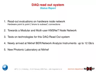
DAQ read out system Status Report. Read-out evaluations on hardware node network Hardware point to point (“shore to subsea”) connections Towards a Modular and Multi-user KM3NeT Node Network Tests on technologies for this DAQ Read Out system

DAQ read out system Status Report
E N D
Presentation Transcript
DAQ read out system Status Report Read-out evaluations on hardware node networkHardware point to point (“shore to subsea”) connections Towards a Modular and Multi-user KM3NeT Node Network Tests on technologies for this DAQ Read Out system Newly arrived at Nikhef BER/Network Analyze Instruments up to 12 Gb/s New Photonic Laboratory at Nikhef
Main Similarities and Differences Status Report 10Gb/s upstream 156 Mb/s downstream • Distributed Asynchronous read-out • Distributed time stamp off shore • Ethernet controlled read-out • Dedicated Synchronous read out • Distributed clocks on shore • Detector wide “heartbeat” read-out
Exploring a modular Multi user KM3NeT Node Network Status Report • A synchronous node design • From shore to each Node e.g. a Story • Synchronous data transport using a single sourced read-out system clockThe “Heartbeat” • Optical Channel connections • The System Clock distribution is proved • Event time-stamp to the PMT data on shore • On Shore Slow Controls/ Timing and/or Trigger controls
Architecture for Km3NeT Avoiding Rayleigh Limitation cw DWDM lasers (up to 100 wavelengths) DWDM Mux 100km fibre path l1 Single fibre feed shared for feed wavelength comb Comms & Timing 1 of 100 fibres Power splitters to feed up to 100 units Up to 100 reflective modulators Data out Optical Amplifiers 2km PMTs Data Receiver WDM Demux l1 DWDM Demux Shore Station OMs Optical receiver Electrical drive to modulator. (single modulator gates all DWDM Wavelengths) Undersea Station
Test bench SPARK Sophisticated Photonic Architecture a Readout for Km3Net clk AWG driver data cw ch 17 17 18 19 R-EAM 17 18 19 clk driver to sub-sea from shore R-EAM DWDM combiner data DWDM cw ch 18 R-EAM clk R-EAM driver data cw tun SOA Xilinx5 FPGA kit Lattice FPGA App. clk receiver data PIN sub-clk clk receiver data PIN from sub-sea to shore DWDM sub-clk sub-sea shore 100 km fiber
10 Gb/s Eye Pattern Received signal after a 10 km connection at receiver output BER = Signal Quality 72.4 mV/div Clock Rec: 10,3125 Gb/s Time 16.2 ps/div Trig: Pattern 5.1 mV LBW 4.13 MHz Delay 40.1552 ns Bit 113
Pulse Transmission over 10 km jitter mainly from P-N change over in the electronic circuitry 48.80 ps
Modular and multi-user KM3NeT Node Network Synchronous Read-Out WP 2, 3, 4, 5 Meeting, 23-24 February 2009 Paris, Jelle Hogenbirk et al. Transparent network for the DAQ system Uses minimum of hardware/functions on the seabed
Node Function description • Analogous to GBT (Gigabit Transceiver) architecture for LHC • Three concurrent functionalities are defined: • . • DAQ data acquisition, • Or synchronous, real-time else asynchronous, store and forward data transport • TTC timing and trigger control • e.g. time controlled triggers for led flashes for calibration purposes. • SC slow control • switching, system checks, value settings etc.
Node Development Kit A vehicle for developments for a minimum of hardware on the seabed • Onshore: • FPGA : • Signal propagation time measurements • The Interface from GbE to SPARK • on-shore or off-shore event time stamp requirements • Slow Control /Timing and Triggering Control requirements • SERDES 10 GB/s deserializer • Some additional photonics among an laser for Bidirectional data • Offshore: • FPGA : • DAQ continuous read out • Timing and Triggering Control requirements • Slow Control / • SERDES 10 Gb/s data serializer
First write-ups for a Node Development Kit an addition to Spark 10Gb/s upstream 156 Mb/s downstream 67 bit words are serialized Using the “Interlaken” Protocol Shore logic CWLASER GbE Ethernet LASER FPGA 10 Gb/s deserializer PIN GPS timing signal 156 Mhz CLK Sphere logic CPLD 156Mb/s FPGA decoder PIN CLK_QPLL Heart Beat 8bit/30 MHz sys clk REAM IC-board 10 Gb/s serializer 4x 3.125 Gb/s PMT signals / 31 bits LVDS
AgilentBER analyzer and TDR analyzer for 12 Gb/s J-BERT N4903A 12.5 Gb/s High Performance Serial BERT Bit Pattern Generator DCA-J 86100 C Digital Communication Analyzer with 86108 A 32 GHz BW Precision Waveform Analyzer or 54754 A 18 GHz Differential TDR Module Sample Oscilloscope and
Agilent Lightwave Multimeter 8163 B with Optical Reference Receiver 81495 A (12 Gb/s) Agilent 8163 B Lightwave Multimeter with 81495A Ref. Receiver