Study of Virtual Resistance Control Loop in AC-AC Converter Operation with Load Transient
140 likes | 278 Vues
Explore a novel control strategy for improved voltage regulation with low harmonic distortion in AC-AC conversion under load transients and nonlinear loads. Includes experimental results, conclusions, and suggestions for future research in power conditioning.

Study of Virtual Resistance Control Loop in AC-AC Converter Operation with Load Transient
E N D
Presentation Transcript
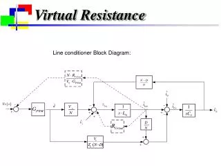
Virtual Resistance Line conditioner Block Diagram:
Experimental Results Prototype
ac-ac converter voltage signals Rectifier Inverter
Operation with Load Transient Without Virtual Resistance Control Loop With Virtual Resistance Control Loop 50% Load Transient
Operation with input Transient • +20% transient in input voltage Vi(t):
Operation with input Transient • -20% transient in input voltage Vi(t):.
Operation with input Transient • THD correction:
Nonlinear load Operation The greatest requirements in terms of dynamic response.
Conclusions • Experimental Results: • The controlstrategywasefficient with instantaneouscorrection of the output voltage when faced with input voltage and load variations; • Capability of supplying an output voltage with low harmonic distortion; • When presented with the worst case scenario, a nonlinear load, the conditioner studied was able to correct the THD to fit the required standards of 5% (IEEE519/92);
Conclusions • Contributions: • A generalization of serial line conditioners was presented through 12 possible topologies; • This work focused on the study of a serial line conditioner with an ac-ac indirect converter with direct link, fed by load side. The capacitive filter was positioned on the load side to make use of the line impedance as a multi-functional filter; • A control strategy was introduced to efficiently stabilize the output voltage of the studied structure; .
Conclusions • Future works: • Study of three-phase voltage line conditioners: - Space vector Modulation; - Digital Control and Nonlinear Control Techniques; - Study of Rectifier control techniques; - Study of combined series and shunt active power filters for simultaneous compensation of voltage and current; - Hybrid and Matrix Converters;