A Historical Background
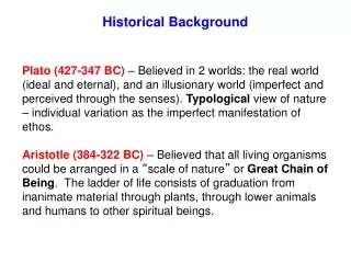
A Historical Background. The idea of calculating with a machine dates to before 500 B.C. when the Babylonians invented the abacus , the first mechanical calculator. Blaise Pascal (1623-1662).

A Historical Background
E N D
Presentation Transcript
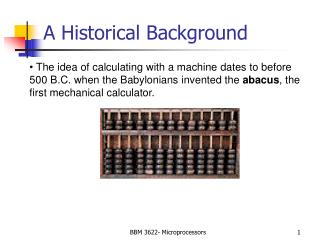
A Historical Background • The idea of calculating with a machine dates to before • 500 B.C. when the Babylonians invented the abacus, the • first mechanical calculator. BBM 3622- Microprocessors
Blaise Pascal (1623-1662) • The abacus was not improved until 1642, when Blaise Pascal invented a calculator constructed a gear and wheels. BBM 3622- Microprocessors
Charles Babbage • One early pioneer of mechanical computing machinery was Charles Babbage and produce a programmable calculating machine in 1823. He create the “Analytical Engine”. This machine was a mechanical computer that stored 1000 20-digit decimal numbers and variable program that could modify the function of the machine. BBM 3622- Microprocessors
Herman Hollerith • In 1889, Herman Hollerith developed the punched card for storing data and also developed a mechanical machine-driven by one of the new electric motors. He was the former of IBM Corporation. BBM 3622- Microprocessors
Konrad Zuse • The first electronic calculating machine invented in 1941 by Konrad Zuse. He had released the first programmable computer designed to solve complex engineering equations. It was also the first machine to work on the binary system, as opposed to the more familiar decimal system. His calculating computer was used in aircraft and missile design during World War II for the German war effort. BBM 3622- Microprocessors
Binary System BBM 3622- Microprocessors
Alan Turing • The first truly electronic computer was places into operation in 1943 to break secret German military codes. The first electronic computer system, which used vacuum tubes, was invented by Alan Turing who is a British mathematician. Turing called this machine Colossus, most likely because its size. A problem with Colossus was that although its design allowed it to break secret German military codes generated by mechanical Enigma machine, it could not solve other problems. Colossus was not programmable- it was a fixed program computer system. BBM 3622- Microprocessors
Sample Turing Machine BBM 3622- Microprocessors
ENIAC • The first general purpose programmable computer system was developed in 1946 and called ENIAC. The ENIAC was a huge machine(30 tons) and performed about 100 000 operation per second. BBM 3622- Microprocessors
John von Neumann • In 1945, Von Neumann contributed a new understanding of how practical fast computers should be organized and built; these ideas, often referred to as the stored-program technique, became fundamental for future generations of high-speed digital computers and were universally adopted. BBM 3622- Microprocessors
Transistor BBM 3622- Microprocessors
INTEL 4004 • The development of transistor in 1948, followed by the invention of the integrated circuits in 1958. In 1971, the first microprocessor Intel 4004 was developed. 4004 was a 4-bit microprocessor and instruction set contains 45 instruction. It performed about 50 000 instruction per second. BBM 3622- Microprocessors
Intel 8086 • In 1978, Intel released the 8086microprocessor which was 16-bit microprocessor and performed 2.5 million instruction per second. • This microprocessor were called CISC(Complex Instruction Set Computers) because of the number and complexity of instructions. • The popularity of Intel family was ensured in 1981 when IBM Corp. decided to use 8088/8086 microprocessors in its personal computers. BBM 3622- Microprocessors
Intel 8086/8088 Microprocessors • Intel 8086 and 8088 Microprocessors are the basis of all IBM-PC compatible computers(8086 introduced in 1978, first IBM-PC released in 1981) • All Intel, AMD and other advanced microprocessors are based on and are compatible with the original 8086/8 • At Power Up and Reset time, Pentiums, Athlons etc all look like 8086 processors BBM 3622- Microprocessors
Intel 8086/8088 Microprocessors • Intel 8086 is a 16-bit microprocessor • 16-bit data registers • 16 or 8 bit external data bus • Some techniques to optimise the CPU performance when it’s executing programs • Segment: Offset memory model • Little-Endian Data Format BBM 3622- Microprocessors
8086/8088 (1) • Original IBM PC used 8088 micrprocessor • 8088 is similar to the 8086 microprocessor but it has an external 8-bit bus & only 4-deep queue • For cost reduction reasons • We can consider 8086 and 8088 together • PC clones often used 8086 for better performance • 8-bit bus reduces performance, but meant cheaper computers BBM 3622- Microprocessors
8086/8088 (2) • Remember the Fetch-Decode-Execute cycle? • Fetching from EXTERNAL MEMORY is SLOW • The 8086/8 used an instruction queue to speed up performance • While the processor is decoding and executing an instruction, its bus interface can be reading new instructions, since at that time the bus is not actually in use BBM 3622- Microprocessors
8086/8088 Functional Units BBM 3622- Microprocessors
8086/8088 (3) • 8086/8088 consists of two internal units • The execution unit (EU) - executes the instructions • The bus interface unit (BIU) - fetches instructions, reads operands and writes results • The 8086 has a 6-byte prefetch queue • The 8088 has a 4-byte prefetch queue BBM 3622- Microprocessors
8086/8088 Internal Organisation BBM 3622- Microprocessors
BIU Elements • Instruction Queue: the next instructions or data can be fetched from memory while the processor is executing the current instruction • The memory interface is slower than the processor execution time so this speeds up overall performance • Segment Registers: • CS, DS, SS and ES are 16-bit registers • Used with the 16-bit Base registers to generate the 20-bit address • Allow the 8086/8088 to address 1Mb of memory • Changed under program control to point to different segments as a program executes • Instruction Pointer (IP) contains the Offset Address of the next instruction, the distance in bytes from the address given by the current CS register
8086/8088 20-bit Addresses BBM 3622- Microprocessors
Memory 00000h 123A0h 157BBh 2239Fh 223A0h 341Bh Exercise: 20-bit Addressing CS=123Ah IP=341Bh Range of Code Segment BBM 3622- Microprocessors
Exercise: 20-bit Addressing • CS contains 0A820h,IP contains 0CE24h. What is the resulting physical address? • CS contains 0B500h, IP contains 0024h. What is the resulting physical address? BBM 3622- Microprocessors
Segment Registers The utilization of the segment registers essentially divides the memory space into overlapping segments, with each segment being 64K bytes long and at an address that is divisible by 16. BBM 3622- Microprocessors
The advantage of using segment registers • Allow the memory capacity to be 1 M Byte even though the addresses associated with the individual instructions are only 16 bits wide. • Allow the instruction, data or stack portion of a program to be more than 64K Bytes long by allowing more than one code, data or stack segment. • Facilitate the use of separate memory areas for a program, its data and the stack. • Permit a program and/or its data to be put into different areas of memory each time the program is executed. BBM 3622- Microprocessors
8086/8 In Circuit (1) • 8086/8 microprocessors need support circuits in a microcomputer system • 8086/8 multiplex the address and data buses on the same pins • This saves pins but at a price: • Demultiplexing logic is needed to build up separate address and data buses to interface with RAMs and ROMs BBM 3622- Microprocessors
Pin Connections • AD15-AD0: (I/O-3) • The 8086 address/data bus lines compose • the upper multiplexed address/data bus on • 8086. These lines contains address bits • whenever ALE is logic 1. These pins enter • a high-impedance state whenever a hold • acknowledge occurs. BBM 3622- Microprocessors
Pin Connections A19/S6-A16/S3: (O-3) The address/status bus bits are multiplexed to provide address signals A19-A16 and also status bits S6-S3. The pins also attain a high-impedance state during the hold acknowledge. S4 and S3 show which segment is accessed during the current bus cycle. BBM 3622- Microprocessors
Pin Connections BBM 3622- Microprocessors
: (O-3) Whenever the read signal is logic 0, the data bus is receptive to data from the memory or I/O devices connected to system. READY: (I) This input is controlled to insert wait states into the timing of the microprocessor. READY=0: P enters into wait states and remain idle READY=1: It has no effect on operation of P Pin Connections BBM 3622- Microprocessors
: (I) The test pin is an input that is tested by the WAIT instruction. NMI: (I) The non-maskable interrupt input is similar to INTR except that the NMI does not check to see if IF flag bit is a logic 1. This interrupt input uses interrupt vector 2. Pin Connections BBM 3622- Microprocessors
RESET: (I) The reset input causes the P to reset itself if this pin is held high for a minimum four clocking periods. It begins executing instructions at memory location FFFF0H and disables future interrupts by clearing the IF flag bit. : (I) Minimum/maximum mode pin select. : (O-3) BHE pin is used to enable the most sig. data bus bits (D15-D8) during a read or write operation. Pin Connections BBM 3622- Microprocessors
: (O-3) The pin selects memory or I/O. This pin indicates that the microprocessor address bus contains either a memory address or an I/O port address. : (O-3) This line indicates that 8086 is outputting data to a memory or I/O device. Minimum mode Pins BBM 3622- Microprocessors
Minimum mode Pins : (O-3) The interrupt acknowledge signal is a response to the INTR input pin. This pin is normally used to gate the interrupt vector number onto the data bus in response to an interrupt request. : (O) Address latch enable shows that the 8086 address/data bus contains address information. This address can be a memory address or an I/O port number. BBM 3622- Microprocessors
Minimum mode Pins :(0-3) The data transmit/receive signal shows that the microprocessor data bus is transmitting or receiving data. : (O-3) Data bus enable activates external data bus buffers. BBM 3622- Microprocessors
Minimum mode Pins HOLD : (I) The hold input requests a direct memory access (DMA). If the HOLD signal is logic 1, the microprocessor stops executing software and places its address, data and control bus at the high- impedance state. HLDA : (O) Hold acknowledge indicates that the 8086 microprocessor entered the hold state. BBM 3622- Microprocessors
Maximum mode Pins • In order to achieve maximum mode for use with external coprocessors or multiprocessing applications. (O) The status bits indicate the function of the current bus cycle. These signals are normally decoded by the 8288 bus controller. BBM 3622- Microprocessors
Satatus bits BBM 3622- Microprocessors
8086/8 In Circuit (2) • In Maximum Mode the 8086/8 needs at least the following: 8288 Bus Controller, 8284A Clock Generator, 74HC373s and 74HC245s • With the aid of these devices the 8086 begins to look like the ideal microprocessor we looked at earlier BBM 3622- Microprocessors
8086/8 Maximum Mode • In maximum mode, the 8288 uses a set of status signals (S0, S1, S2) to rebuild the normal bus control signals of the microprocessor • MRDC#, MWTC#, IORC#, IOWC# etc • Equivalent to MEMR# etc • Look at some special signals briefly BBM 3622- Microprocessors
74LS373 Octal Transparent Latch with 3-state Outputs BBM 3622- Microprocessors
74LS245 Octal Bus Tranceiver BBM 3622- Microprocessors
RESET# Signal • The Active low RESET# signal puts the 8086/8 into a defined state • Clears the flags register, segment registers etc. • Sets the effective program address to 0FFFF0h (CS=0F000h, IP=0FFF0h) • 8086/8 Programs always start at FFFF0H after Reset has been asserted and removed • Continues into latest generation CPUs BBM 3622- Microprocessors
BHE# Signal (8086 Only) • The 8086 processor can address memory a byte at a time • Its data bus is 16-bits wide • It uses the BHE# signal and A0 (sometimes called BLE#) to address bytes using its 16-bit bus BBM 3622- Microprocessors
Use of BHE#/A0(BLE#) BBM 3622- Microprocessors
BHE# A0/BLE# Selection 0 0 Whole word (16-bits) 0 1 High byte to/from odd address 1 0 Low byte to/from even address 1 1 No selection Use of BHE#/BLE# BBM 3622- Microprocessors