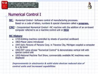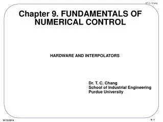
Unit 5 Numerical Control
Unit 5 Numerical Control. Sections: Fundamentals of NC Technology Computer Numerical Control Distributed Numerical Control Applications of NC NC Part Programming. Numerical Control (NC) Defined.

Unit 5 Numerical Control
E N D
Presentation Transcript
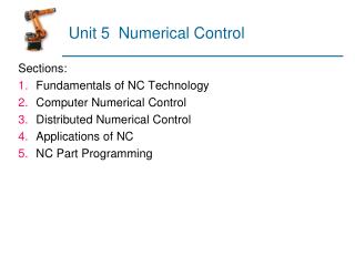
Unit 5 Numerical Control Sections: • Fundamentals of NC Technology • Computer Numerical Control • Distributed Numerical Control • Applications of NC • NC Part Programming
Numerical Control (NC) Defined Programmable automation in which the mechanical actions of a ‘machine tool’ are controlled by a program containing coded alphanumeric data that represents relative positions between a work head (e.g., cutting tool) and a work part Program Instructions Machine Control Unit Transformation Process Power
NC Coordinate Systems For flat and prismatic (block-like) parts: • Milling and drilling operations • Conventional Cartesian coordinate system • Rotational axes about each linear axis For rotational parts: • Turning operations • Only x- and z-axes
Motion Control Systems Point-to-Point systems • Also called position systems • System moves to a location and performs an operation at that location (e.g., drilling) • Also applicable in robotics Continuous path systems • Also called contouring systems in machining • System performs an operation during movement (e.g., milling and turning)
Interpolation Methods • Linear interpolation • Straight line between two points in space • Circular interpolation • Circular arc defined by starting point, end point, center or radius, and direction • Helical interpolation • Circular plus linear motion • Parabolic and cubic interpolation • Free form curves using higher order equations
Absolute vs. Incremental Positioning • Absolute positioning • Move is: x = 40, y = 50 • Incremental positioning • Move is: x = 20, y = 30.
Computer Numerical Control (CNC) • Storage of more than one part program • Various forms of program input • Program editing at the machine tool • Fixed cycles and programming subroutines • Interpolation • Acceleration and deceleration computations • Communications interface • Diagnostics
DNC • Direct numerical control (DNC) – control of multiple machine tools by a single (mainframe) computer through direct connection and in real time • 1960s technology • Two way communication • Distributed numerical control (DNC) – network consisting of central computer connected to machine tool MCUs, which are CNC • Present technology • Two way communication
Distributed Numerical Control Central Computer NC Pgms Computer Network BTR BTR BTR Machine Control Unit Machine Control Unit Machine Control Unit Transformation Process
NC Application Characteristics (Machining) • Batch and High Volume production • Repeat and/or Repetitive orders • Complex part geometries • Mundane operations • Many separate operations on one part
Cost-Benefits of NC Costs • High investment cost • High maintenance effort • Need for skilled programmers • High utilization required Benefits • Cycle time reduction • Nonproductive time reduction • Greater accuracy and repeatability • Lower scrap rates • Reduced parts inventory and floor space • Operator skill-level reduced
NC Part Programming • Manual part programming • Manual data input • Computer-assisted part programming • Part programming using CAD/CAM
Manual Part Programming Binary Coded Decimal System • Each of the ten digits in decimal system (0-9) is coded with four-digit binary number • The binary numbers are added to give the value • BCD is compatible with 8 bits across tape format, the original storage medium for NC part programs • Eight bits can also be used for letters and symbols
Creating Instructions for NC • Bit - 0 or 1 = absence or presence of hole in the tape • Character - row of bits across the tape • Word - sequence of characters (e.g., y-axis position) • Block - collection of words to form one complete instruction • Part program - sequence of instructions (blocks)
Block Format Organization of words within a block in NC part program • Also known as tape format because the original formats were designed for punched tape • Word address format - used on all modern CNC controllers • Uses a letter prefix to identify each type of word • Spaces to separate words within the block • Allows any order of words in a block • Words can be omitted if their values do not change from the previous block
Types of Words N - sequence number prefix G - preparatory words • Example: G00 = PTP rapid traverse move X, Y, Z - prefixes for x, y, and z-axes F - feed rate prefix S - spindle speed T - tool selection M - miscellaneous command • Example: M07 = turn cutting fluid on
Example: Word Address Format N001 G00 X07000 Y03000 M03 N002 Y06000
Cutter Offset Cutter path must be offset from actual part outline by a distance equal to the cutter radius
Issues in Manual Part Programming • Adequate for simple jobs, e.g., PTP drilling • Linear interpolation G01 G94 X050.0 Y086.5 Z100.0 F40 S800 • Circular interpolation G02 G17 X088.0 Y040.0 R028.0 F30 • Cutter offset G42 G01 X100.0 Y040.0 D05
Manual Data Input • Machine operator does part programming at machine • Operator enters program by responding to prompts and questions by system • Monitor with graphics verifies tool path • Usually for relatively simple parts • Ideal for small shop that cannot afford a part programming staff • To minimize changeover time, system should allow programming of next job while current job is running
Computer-Assisted Part Programming • Write machine instructions using natural language type statements • Statements translated into machine code of the MCU • APT (Automatically Programmed Tool) Language
Sample Statements • Part is composed of basic geometric elements and mathematically defined surfaces • Examples of statements: P4 = POINT/35,90,0 L1 = LINE/P1,P2 C1 = CIRCLE/CENTER,P8,RADIUS,30 • Tool path is sequence of points or connected line and arc segments • Point-to-Point command: GOTO/P4 • Continuous path command: GOLFT/L1,TANTO,C1
YouTube • CNC Milling • CNC Punching • CNC Adhesive Bonding • CNC Drug Insertion • CNC Bioprocessing • CAD/CAM • Etc.