Computer Numerical Control
Computer Numerical Control. Eastern Mediterranean University Computer Integrated Manufacturing MENG 364 Fall 2013. Computer Numerical Control. Numerical Control: Definition: A form of programmable automation in which the process is controlled by numbers, letters and symbols. .

Computer Numerical Control
E N D
Presentation Transcript
Computer Numerical Control Eastern Mediterranean University Computer Integrated Manufacturing MENG 364 Fall 2013
Computer Numerical Control Numerical Control: Definition: A form of programmable automation in which the process is controlled by numbers, letters and symbols.
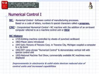
Historical Background • In late 1940s, John T Parsons conceived a method of using punched cards containing coordinate position data to control m/c tool. The m/c was directed to move in small increments, thus generating desire surface of an airfoil. • Later Parsons demonstrated his work to US air force . The force sponsored a series of projects at MIT. The 1st development at MIT was a prototype NC milling m/c by retrofitting a conventional tracer mill m/c with position servomechanisms for three m/c tool axes. • The first demonstration was held in 1952. In 1953, the usefulness had been proven. Shortly thereafter, m/c tool builders launched projects for developing commercial NC units, thus creating a revolution. • Further sponsorship of air force devised a NC language called APT. Though it is considered lengthy and complex, many advanced languages are based on APT.
Basic Components of NC System An NC system consists of following 3 basic components: • Program of instructions • Controller Unit, also called m/c control unit (MCU) • M/C tool General relationship among three components is shown in Fig.
Basic Components of NC System(1. Program of Instructions) • This is detailed step by step set of directions which will tell the m/c tool what to do. • The most common input medium used is 1 inch wide punched tape. Other input mediums are punched cards, magnetic tape Punched tape Punched card Magnetic tape: plastic film with magnetic coating
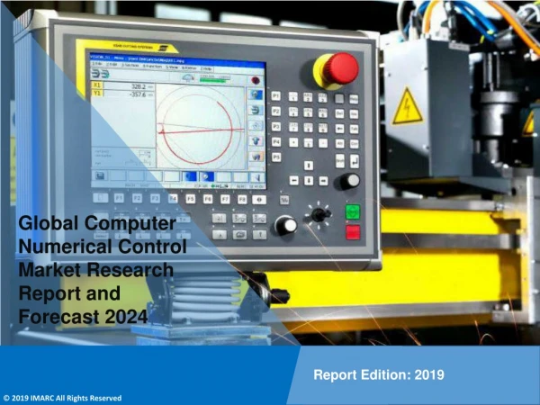
Basic Components of NC System(2. Controller Unit) • Controller unit consists of electronics hardware that read and interpret the program of instructions and convert it into mechanical actions of m/c tool.
Basic Components of NC System(3. Machine Tool) • It is the part of NC system which performs useful work. • Milling m/c tool is an example of NC system • Fixtures, cutting tools, auxiliary equipment needed in machining operation are part of m/c tool • A machining center can perform several functions: • It is capable of performing various operations: drilling, tapping, reaming, milling, boring • It has capacity to change tool automatically under tape command. (c) Several tools are kept in magazine. The magazine rotates and position the desired tool. The automatic tool changer automatically picks the tool and inserts into spindle.
NC Procedure Process Planning: The drawing of work part must be interpreted in terms of manufacturing processes to be used. This step is referred as process planning and it is concerned with route sheet. The route sheet is listing of the sequence of operations which must be performed on work part. It is called rout sheet because it also lists machines through which the part must be routed .
NC Procedure • Part Programming: The programmer plans the sequence of machining steps to be performed by NC and to document these in in a special format. The are two ways of programming: • Manual part programming: The machining instructions are prepared manually on a form called program manuscript. • Computer assisted part programming: Machining instructions are created with the aid of computer. This saves much time and is useful for complex parts.
NC Procedure • Tape Preparation: • In manual programming, the punched tape is prepared directly from the part program manuscript on a type-writer like device equipped with the tape punching capability. • In computer-assisted programming, the computer interprets the list of part programming instructions, performs the necessary calculations to convert this into a detailed set of m/c tool motion commands, and then controls a tape punch device to prepare tape for specific NC m/c.
NC Procedure 4. Tape Verification: After the punch tape has been prepared, a method is usually provided for checking accuracy of tape. Some time the tape is checked by running it through a computer program which plots various tool movements (or table movements). In this way, major errors in tape can be discovered. Another method is Acid test. In this test, foam or plastic material is used to make a part. Then the error can be detected easily. 5. Production: The final step in NC procedure is to use NC tape in production. Raw material is clamped in fixture, tools are selected and holded in spindle. The zero point on job is selected and machining is begun.
NC Coordinate Systems • In order for the part programmer to plan the sequence of positions and movements of the cutting tool relative to work piece, it is necessary to establish a standard axis system by which the relative positions can be specified. • Ref Fig, two axes x & y are defined in plane of table and z axis is perpendicular to this plane; and movement in z direction is controlled by vertical motion of spindle. • In addition to 3 axes, the machines (especially NC milling) can posses capacity to control one or more rotational axes. These are a, b and c, which specify angles about x, y & z axes, respectively.
NC Coordinate Systems(Fixed Zero & Floating Zero) The programmer must determine position of tool relative to origin (zero point) of coordinate system. NC machines have two methods for specifying zero point: Fixed Zero: In this case the origin is always located at the same position on m/c table. Usually this is the southwest corner of table and all tool locations will be defined by positive x & y coordinates. Floating Zero: The second and more common feature on modern NC machines allows the m/c operator to set zero point at any position on m/c table.
NC Coordinate Systems(Absolute and incremental positioning) • Absolute Positioning: In this method, the tool position is always defined with respect to zero point/origin of coordinate system. • Incremental Positioning: In this method, the tool position is defined with respect to previous position of tool on work-piece.
NC Motion Control Systems(Point-to-point NC) • Point to point is also sometimes called positioning system • In PTP, the objective of m/c tool control system is to move cutting tool to a pre-defined location • The speed or path by which this movement is accomplished is not important in PTP NC. • Once the tool reaches the desired location, machining operation is performed at that location. Example: NC drill presses are good example of PTP system. The spindle must be positioned at a particular location on w/p. This is done under PTP control.
A (X,Y) Coordinate System Y-axis (1,.875) X-axis Origin
3D Coordinate System (X,Y,Z) Z-axis Y-axis X-axis
Basic Machine Axes: 3 axis • Milling Machines: 3 axis X – axis (table left and right) Y – axis (table in and out) Z – axis (usually the spindle axis)
Additional Axes • A – axis (angular axis about X - axis) • B – axis (angular axis about Y – axis) • C – axis (angular axis about Z – axis) • U – axis (secondary axis parallel to X) • V – axis (secondary axis parallel to Y) • W – axis (secondary axis parallel to Z)
G - Code Programming • G – Code Programming • Originally called the “Word Address” programming format. • Processed one line at a time sequentially.
Common Format of a Block Sequence # Preparatory Function Dimension Words Feed Rate Spindle Function Tool Function Misc. Function N50 G90 G01 X1.40Y2.25 F10 S1500 T01 M03 Individual Words
Word Address 1 • N – Sequence or line number • A tag that identifies the beginning of a block of code. It is used by operators to locate specific lines of a program when entering data or verifying the program operation. • G – Preparatory function • G words specify the mode in which the milling machine is to move along its programmed axes.
Word Address 2 • Dimension Words X – Distance or position in X direction Y – Distance or position in Y direction Z – Distance or position in Z direction • M – Miscellaneous functions • M words specify CNC machine functions not related to dimensions or axial movements.
Word Address 3 • F – Feed rate(inches per minute or millimeters per minute) • Rate at which cutting tool moves along an axis. • S – Spindle speed(rpm – revolutions per minute) • Controls spindle rotation speed. • T – Tool number • Specifies tool to be selected.
Word Address 4 • I – Circular cutting reference for x axis • J – Circular cutting reference for y axis • K – Circular cutting reference for z axis
Manual Part Programming Methods(Groups of G codes) Commonly used G codes in form of groups: • Coordinate system Group (G90, G91) Absolute programming using G90: - G90 is used for specifying tool position in absolute coordinate system. - Ref. Fig, suppose the tool has to pass through the route: O-A-B-C. Then blocks will be: N001 G90 G01 X5.0 Y10.0 F200 N002 X25 .0 Y15.0 N003 X35.0 Y5.0 - This system is generally advised for programming because there are few chances of errors. - Whatever the route of move, programmed X &Y values of each position remain the same. Incremental programming G91: - G91 is generally default mode and is cancelled with G90. End of program words (M02, M30) also cancel them. • Ref to Fig, the incremental programming for path O-A-B-C: • N001 G91 G01 X5.0 Y10.0 F200 • N002 X20.0 Y5.0 • N003 X10.0 Y-10.0
Manual Part Programming Methods(Groups of G codes) Linear and Rapid interpolation (G01 &G00) • This code is used when material needs to be cut using feed rate • Say material needs to be cut at feed rate of 250mm/min from point D-E (Fig.), the program of block will be: N01 G90 G00 X20.0 Y100.0 (Absolute Programming) N02 G01 X110.0 Y30.0 F250 (F function is added)
Manual Part Programming Methods(Groups of G codes) (c) Circular interpolation: • When an arc is to be traversed in a plane, the G02 (CW) or G03 (CCW) is used. • Ref Fig, the program block for F-G: N01 G90 G00 X65.0 Y60.0 (CCW- Absolute) N02 G03 X15.0 Y30.0 I-50.0 J-40.0 F 200.0 (I, J can be replaced by R). - - R can not be used for full circle. In such case, I, J need to be used. - If motion is CCW from G-F -