
Scalable Campus Wired LAN Designs with Cisco Validated Models
E N D
Presentation Transcript
LAN Design FidelinaAnastasiia, 21/06/2019
Sections & Objectives • 1.1 Campus Wired LAN Designs • Explain why it is important to design a scalable hierarchical network. • Describe hierarchical small business network designs. • Explain considerations for designing a scalable network.
Cisco Validated DesignsThe Need to Scale the Network • A company with a small network with one site and a connection to the Internet might grow into an enterprise with a central location with numerous remote sites across the globe. • All enterprise networks must: • Support the exchange of various types of network traffic • Support critical applications • Support converged network traffic • Support diverse business needs • Provide centralized administrative control • The LAN is the networking infrastructure that provides access to network resources for end users over a single floor or a building.
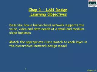
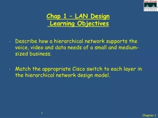
Cisco Validated DesignsHierarchical Design Model • The campus wired LAN uses a hierarchical design model to break the design up into modular layers. • Breaking the design up into layers allows each layer to implement specific functions, which simplifies the network design for easier deployment and management. • A hierarchical LAN design includes three layers as shown in the figure: • Access layer • Distribution layer • Core layer • Some smaller enterprise networks implement a two-tier hierarchical design and collapse the core and distribution layers into one layer.
Expanding the NetworkDesign for Scalability • The network designer must develop a strategy to enable the network to be available and scale easily and effectively. • Use expandable, modular equipment or clustered devices that can be easily upgraded to increase capabilities. • Design a hierarchical network to include modules that can be added, upgraded, and modified as needed. • Create an IPv4 or IPv6 address strategy that is hierarchical. • Choose routers or multilayer switches to limit broadcasts and filter undesirable traffic from the network. • Implement redundant links between critical devices and between access and core layers.
Overview of VLANsVLAN Definitions • VLANs are mutually isolated and packets can only pass between VLANs via a router. • VLANs can segment LAN devices without regard for the physical location of the user or device. • In the figure, IT users on the first, second, and third floors are all on the same LAN segment. The same is true for HR and Sales users. • A VLAN is a logical partition of a Layer 2 network. • Multiple partitions can be created and multiple VLANs can co-exist. • The partitioning of the Layer 2 network takes place inside a Layer 2 device, usually via a switch. • Each VLAN is a broadcast domain that can span multiple physical LAN segments. • Hosts on the same VLAN are unaware of the VLAN’s existence.
VLANs in a Multi-Switched EnvironmentTagging Ethernet Frames for VLAN Identification • Switches add VLAN tagging information after the Source MAC address field. • The fields in the 802.1Q VLAN tag includes VLAN ID (VID). • Trunk links add the tag information before sending the frame and then remove the tags before forwarding frames through non-trunk ports. • Before a frame is forwarded across a trunk link, it must be tagged with its VLAN information. • Frame tagging is the process of adding a VLAN identification header to the frame. • It is used to properly transmit multiple VLAN frames through a trunk link. • IEEE 802.1Q is a vey popular VLAN trunking protocol that defines the structure of the tagging header added to the frame.
Inter-VLAN Routing OperationRouter-on-a-Stick Inter-VLAN Routing • In this example, the R1 interface is configured as a trunk link and connects to the trunk F0/4 port on S1. • Router accepts VLAN-tagged traffic on the trunk interface • Router internally routes between the VLANs using subinterfaces. • Router then forwards the routed traffic as VLAN-tagged for the destination VLAN out the trunk link. • The router-on-a-stick approach uses only one of the router’s physical interface. • One of the router’s physical interfaces is configured as a 802.1Q trunk port so it can understand VLAN tags. • Logical subinterfaces are created; one subinterface per VLAN. • Each subinterface is configured with an IP address from the VLAN it represents. • VLAN members (hosts) are configured to use the subinterface address as a default gateway.
Inter-VLAN Routing OperationRouter-on-a-Stick Inter-VLAN Routing
VTP ConfigurationVTP Configuration Overview • Steps to Configure VTP: • Step 1 - Configure the VTP Server • Step 2 - Configure the VTP Domain Name and Password • Step 3 - Configure the VTP Clients • Step 4 - Configure VLANs on the VTP Server. • Step 5 - Verify the VTP clients have received the new VLAN information.
Layer 3 Switching Operation and ConfigurationInter-VLAN Routing with Switch Virtual Interfaces (Cont.) • An SVI is a virtual interface that is configured within a multilayer switch: • To provide a gateway for a VLAN so that traffic can be routed into or out of that VLAN. • To provide Layer 3 IP connectivity to the switch. • To support routing protocol and bridging configurations. • Advantages of SVIs: • Faster than router-on-a-stick. • No need for external links from the switch to the router for routing. • Not limited to one link. Layer 2 EtherChannels can be used to get more bandwidth.
Expanding the NetworkFailure Domains • A well-designed network should limit the size of failure domains. • A failure domain is the area of a network that is impacted when a critical device or network service experiences problems. • The function of the devices that fail will determine the impact of the failure domain. • Use redundant links and reliable enterprise-class equipment to minimize the disruption in a network. • Smaller failure domains reduce the impact of a failure but also make troubleshooting easier.
Expanding the NetworkPlanning for Redundancy • Redundancy is an important part of the network design for preventing disruption of network services. • Minimize the possibility of a single point of failure by recognizing these facts: • Installing duplicate equipment and providing failover services for critical devices is necessary. • Redundant paths offer alternate physical paths for data to traverse the network. • Spanning Tree Protocol (STP) is required with redundant paths in a switched Ethernet network to prevent Layer 2 loops. • STP provides a mechanism for disabling redundant paths in a switched network until the path is necessary such as when a failure occurs.
Varieties of Spanning Tree ProtocolsCharacteristics of Spanning Tree Protocols
Varieties of Spanning Tree Protocols • Original 802.1D defines a common spanning tree • One spanning tree instance for the switched network (no matter how many VLANs) • No load sharing • One uplink must block for all VLANs • Low CPU utilization because only one instance of STP is used/clculated
Varieties of Spanning Tree ProtocolsOverview • Rapid PVST+ speeds up STP recalculations and converges quicker • Cisco version of RSTP • Two new port types • Alternate port (DIS) • Backup port • Independent instance of RSTP runs for each VLAN • Cisco features such as UplinkFast and BackboneFast are not compatible with switches that run RSTP
Varieties of Spanning Tree ProtocolsEdge Ports Edge port Edge port Has an end device connected – NEVER another switch Immediately goes to the forwarding state Functions similar to a port configured with Cisco PortFast Use the spanning-tree portfastcommand
STP Configuration IssuesSpanning Tree Failure Consequences NEVER turn STP off; this can cause a switched network to be unusable – Remember that there is not a TTL mechanism at Layer 2.
Switch Stacking and Chassis AggregationSpanning Tree and Switch Stacks Diameter of 9 from S1-4 to S3-4 With stacked switches, the diameter is now 3 • Each stack appears as one spanning tree instance • Can add switches without affecting the STP diameter (the maximum number of switches data must cross to connect between any two switches) • IEEE recommends a maximum diameter of 7 switches for default STP timers • Default STP timers are hello – 2 seconds, max age – 20 seconds, forward delay timer – 15 seconds
Link AggregationIntroduction to Link Aggregation Redundant Links with STP (by default blocked) • It is possible to combine the number of physical links between switches to increase the overall speed of switch-to-switch communication. • STP will block redundant links to prevent routing loops.
Expanding the NetworkIncreasing Bandwidth • In a hierarchical network design, some links between access and distribution layer switches may need to process a greater amount of traffic than other links do. • As multiple links converge into a single link, it is possible for this link to become a bottleneck. • EtherChannel is a form of link aggregation that will allow the network administrator to increase the amount of bandwidth between devices by creating one logical link out of several physical links. • EtherChannel uses existing switch ports. • The EtherChannel configuration takes advantage of load balancing between links that are part of the same EtherChannel.
EtherChannel OperationImplementation Restrictions • EtherChannel Restrictions • Interface types cannot be mixed.(Fast Ethernet + Gigabit Ethernet cannot be grouped.) • Provides full-duplex bandwidth up to 800 Mbps (Fast EtherChannel) or 8 Gbps (Gigabit EtherChannel) • Cisco IOS Switch can support 6 EtherChannels. • Created between two switches or a server and switch. • If one side is configured as trunk, the other side must be a trunk within same native VLAN. • Each EtherChannelhas a logical port channel interface and changes to a channel affects its physical interfaces. EtherChannel groups multiple physical ports into one or more logical EtherChannel links.
Concept of First Hop Redundancy ProtocolsDefault Gateway Limitations
Concept of First Hop Redundancy ProtocolsDefault Gateway Limitations • A mechanism is needed to provide alternate default gateways in switched networks where two or more routers are connected to the same VLANs. • Note: In the graphic, a multilayer switch is acting as the default gateway and used for routing. • In a switched network, each client receives only one default gateway. • There is no way to use a secondary gateway, even if a second path exists to carry packets off the local segment. • In the figure, R1 is responsible for routing packets from PC1. If R1 becomes unavailable, R2 can route packets that would have gone through R1. • End devices are typically configured with a single IP address for a default gateway. • If that default gateway IP address cannot be reached, the local device is unable to send packets off the local network.
Concept of First Hop Redundancy ProtocolsRouter Redundancy • To prevent a single point of failure at the default gateway, implement a virtual router. • Present the illusion of a single router to the hosts on the LAN. • By sharing an IP address and a MAC address, two or more routers can act as a single virtual router. • IPv4 address of the virtual router is configured as the default gateway for the workstations on a specific IPv4 segment. • ARP resolution returns the MAC address of the virtual router. • Physical router that forwards traffic is transparent to the host devices. • A redundancyprotocol provides the mechanism for determining which router should take the active role in forwarding traffic. • Ability of a network to dynamically recover from the failure of a device acting as a default gateway is known as first-hop redundancy.
Concept of First Hop Redundancy ProtocolsFirst Hop Redundancy Protocols (Cont.) • Virtual Router Redundancy Protocol version 2 - A nonproprietary protocol that dynamically assigns responsibility for one or more virtual routers to the VRRP routers on an IPv4 LAN. • One router is elected as the virtual router master, with the other routers acting as backups, in case the virtual router master fails. • VRRPv3 - Capability to support IPv4 and IPv6. • Gateway Load Balancing Protocol (GLBP) - Cisco-proprietary FHRP that protects data traffic from a failed router or circuit allowing load balancing between a group of redundant routers. • GLBP for IPv6 - Cisco-proprietary FHRP providing the same functionality of GLBP.
Expanding the NetworkFine-tuning Routing Protocols • OSPF supports a two-layer hierarchical design, referred to as multiarea OSPF. • Multiarea OSPF requires an Area 0 (backbone area) • Non-backbone areas must be directly connected to Area 0. • Advanced routing protocols, such as OSPF and EIGRP are used in large networks. • Link-state routing protocols such as OSPF works well for larger hierarchical networks where fast convergence is important. • Single Area OSPF has one area – Area 0. • Cisco’s proprietary distance vector routing protocol, called EIGRP, is another popular routing protocol. It is designed for larger networks using primarily Cisco routers. • Although the configuring EIGRP is simple, the underlying features and options of EIGRP are extensive and robust.
Cisco Validated DesignsHierarchical Design Model • The campus wired LAN uses a hierarchical design model to break the design up into modular layers. • Breaking the design up into layers allows each layer to implement specific functions, which simplifies the network design for easier deployment and management. • A hierarchical LAN design includes three layers as shown in the figure: • Access layer • Distribution layer • Core layer • Some smaller enterprise networks implement a two-tier hierarchical design and collapse the core and distribution layers into one layer.
NAT CharacteristicsIPv4 Private Address Space (Cont.) • Private IP addresses cannot be routed over the Internet. • NAT is used to translate private IP addresses to public addresses that can be routed over the Internet. • One public IPv4 address can be used for thousands of devices that have private IP addresses.
NAT CharacteristicsWhat is NAT? Important Concept—NAT is enabled on one device (normally the border or edge router) • Private IP addresses cannot be routed over the Internet. • NAT is used to translate private IP addresses used inside a company to public addresses that can be routed over the Internet. • NAT hides internal IPv4 addresses from outside networks. • Companies use the same private IPv4 addresses so outside devices cannot tell one company’s 10.x.x.x network from another company’s 10.x.x.x network. • A NAT-enabled router can be configured with a public IPv4 address. • A NAT-enabled router can be configured with multiple public IPv4 addresses to be used in a pool or NAT pool for internal devices configured with private addresses.
Configure PATAnalyzing PAT PC1 and PC2 open a web browser for a connection to a web server. R2 receives the packets on the inside interface and checks if translation should be performed (via an ACL). R2 assigns the IP address of the outside interface, adds a port number, and creates a NAT table entry for both packets. R2 replaces the inside local source address on each packet with the translated inside global address.
Switch HardwarePacket Tracer – Comparing 2960 and 3560 Switches
Router HardwareRouter Requirements • Routing is required within the distribution layer of an enterprise network. Without routing, packets could not leave the local network. • Routers are critical networking devices because they are responsible for: • Connecting businesses and homes to the Internet • Interconnecting multiple sites within an enterprise network • Connecting ISPs on the Internet • Translating between different media types and protocols • Finding alternate paths if a link or path goes down