Performance Analysis of OFDMA in 802.11ax Networks
630 likes | 660 Vues
Explore OFDMA performance in 802.11ax networks through PHY/MAC simulations across different topologies, UL and DL operations, and various scheduling strategies. Evaluate throughput, latency, and impact on network performance.

Performance Analysis of OFDMA in 802.11ax Networks
E N D
Presentation Transcript
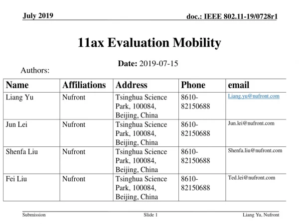
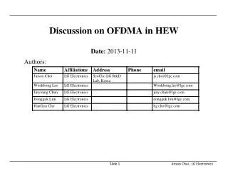
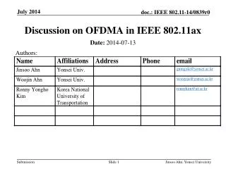
OFDMA performance in 11ax Date: 2015-09-14 Authors: Suhwook Kim, LG Electronics
Introduction • The performance of OFDMA depends on both PHY and MAC, i.e., OFDMA resource unit structure, traffic and scheduling, feedback and link adaptation, and etc. • This contribution addresses OFDMA performance using PHY/MAC integrated simulator • Based on the new PHY structure and numerology which have been agreed in specification framework document [1] • Based on three topologies • Topology 1, 2 is one BSS case and • Topology 3 is OBSS case (residential scenario (SS1)) [2] Suhwook Kim, LG Electronics
Simulation Setup: OFDMA operation • UL operation Suhwook Kim, LG Electronics
Simulation Setup: OFDMA operation • UL operation • AP sends trigger frame by contending with AC_BE • Trigger frame is transmitted by MCS 0, duplicated format in every 20 MHz channels (assuming 74 bytes long) • STAs which are allocated by trigger frame send data frame • MCS, transmission subband, and maximum frame length of data frame are addressed in the trigger frame • If the station doesn’t have any queued data frame, it doesn’t send anything • If the station doesn’t have enough data frame to fill maximum frame length, it adds padding bits to data frame • STAs don’t perform CCA • AP sends each BA frame in same subband with its data frame • BA frame is transmitted by MCS 0 • Contending of STAs is not permitted Suhwook Kim, LG Electronics
Simulation Setup: OFDMA operation • DL operation Suhwook Kim, LG Electronics
Simulation Setup: OFDMA operation • DL operation • AP sends data frame by contending with AC_BE • If AP doesn’t have enough data frame to 4 stations, some subband can be empty and wasted • The STA in head of AP’s queue should be selected as primary destination • Frame length is determined by primary destination • Padding bits can be used in secondary destinations • STA sends each BA frame in same subband with its data frame • BA frame is transmitted by MCS 0 Suhwook Kim, LG Electronics
Simulation Setup: Scheduler • Scheduling resource • Maximum allocation per one station is 1 RU • 1 RU: 242-tone (total 4 RUs in 80 MHz) • Two simple scheduling policy • Random • AP selects STAs randomly • Queue length • AP selects STAs in order of each queue’s length • In DL case, • primary destination is fixed (Head of AP’s queue) • frame length is determined by A-MPDU length to primary destination (legacy spec rule) Suhwook Kim, LG Electronics
Random Scheduler • Example • UL case • AP selects four STAs randomly in STA A ~ F • DL case • STA B is determined as primary destination • AP selects three STAs randomly in STA C, STA A, STA D, and STA E Suhwook Kim, LG Electronics
Queue length Scheduler • Example • UL case • AP selects STA F, E, C, A in order of each queue’s length • DL case • STA B is determined as primary destination • AP selects STA A, E • STA C or D will be selected • randomly Suhwook Kim, LG Electronics
Simulation Setup: Frame length and padding • Example • UL case • DL case Suhwook Kim, LG Electronics
Simulation Setup: Parameters * The transmission latency is measured from the time that MAC receives a packet till the time that PHY starts transmitting. Suhwook Kim, LG Electronics
Simulation Setup: Topologies • We used 3 topologies to analysis OFDMA performance in 11ax • Topology 1 and 2 are single BSS case • Pathlosses between AP and each STA are homogeneous in topology 1 • But they are heterogeneous in topology 2 • By topology 1 and 2, we can verify general OFDMA operation and scheduling scheme • Topology 3 is modified residential scenario in SS1 • By topology 3, we can expect performance gain of 11ax OFDMA in OBSS environment Suhwook Kim, LG Electronics
Topology 1 • Topology description • 1 AP and 10 STAs • AP and all STAs are co-located • Simulation setting • Fixed MCS • MCS 0: 8.6 Mbps in 242 tones (total 34.4 Mbps) • MCS 9: 114.7 Mbps in 242 tones (total 454.8 Mbps) • Traffic; CBR • DL only or UL only • High rate: 4 Mbps per STA in MCS 0, 50 Mbps per STA in MCS9 • Low rate: 2 Mbps per STA in MCS 0, 20 Mbps per STA in MCS9 • TXOP limit: 5 msec in DL only, 4.6 msec in UL only Suhwook Kim, LG Electronics
Topology 1 – UL Throughput performance • High rate traffic • Low rate traffic • Observation • High rate traffic : Throughput gain is 40~50%. The main factors of throughput gain are resolving collision and new PHY structure • Low rate traffic : OFDMA couldn’t show meaningful throughput gain because legacy network can support traffic load Suhwook Kim, LG Electronics
Topology 1 – UL Latency performance • High rate traffic • Low rate traffic • Observation • High rate traffic: Latency gain is 30~50%. • Low rate traffic: Latency gain is about 90%. AP sent trigger frame very frequently, so STAs can send data without contending Suhwook Kim, LG Electronics
Topology 1 – DL Throughput performance • High rate traffic • Low rate traffic • Observation • High rate traffic : Throughput gain is about 20%. Collision resolving effect disappeared in DL case. Only numerology gain remained • Low rate traffic : No OFDMA gain Suhwook Kim, LG Electronics
Topology 1 – DL Latency performance • High rate traffic • Low rate traffic • Observation • High rate traffic: Latency gain is 20~40%. • Low rate traffic: Latency gain is 20~80%. Suhwook Kim, LG Electronics
Topology 2 • Topology description • 1 AP and 10 STAs • Simulation setting • Fixed MCS • TXOP limit: 5 msec • Traffic • DL only or UL only • High rate: 115 Mbps per STA • Low rate: 25 Mbps per STA Suhwook Kim, LG Electronics
Topology 2 – Throughput performance • High rate traffic • Low rate traffic • Observation • High rate traffic : UL throughput gain is about 50% and DL gain is 20%. Gain is similar with topology 1 • Low rate traffic : DL gain is very low, but UL gain is very high. Because there is hidden terminal problem in legacy network, so legacy network shows very low throughput Suhwook Kim, LG Electronics
Topology 2 – Latency performance • High rate traffic • Low rate traffic • Observation • High rate traffic: Latency gain is 20~60%. Gain is similar with topology 1 • Low rate traffic: Latency gain is 60~90%. Generally latency gain is more higher in low rate traffic case than in high rate traffic Suhwook Kim, LG Electronics
Topology 3 • Topology description • 20 APs (Fixed location: center of room) • 4 or 10 STAs per one AP (Random location) • Simulation setting • Open Loop Link Adaption [1] • Traffic • DL only or UL only • High rate: 20 Mbps per STA in 4-STA-SIM, 8 Mbps per STA in 10-STA-SIM • Low rate: 2 Mbps per STA • TXOP limit: 5 msec • Channelization: Random choice in three channels Suhwook Kim, LG Electronics
Topology 3 – UL Throughput performance • High rate traffic • Low rate traffic • Observation • High rate traffic : Throughput gain is 30~70%. • Low rate traffic : Throughput gain is 30~250%. Even though traffic load is very low, legacy network couldn’t fully support that traffic because of OBSS interference and hidden terminal. But OFDMA can support. Suhwook Kim, LG Electronics
Topology 3 – UL Latency performance • High rate traffic • Low rate traffic • Observation • High rate traffic: Latency gain is 40~90%. • Low rate traffic: Latency gain is 25~80%. Unlike topology 1 and 2, latency gain is higher in high rate traffic than low rate traffic Suhwook Kim, LG Electronics
Topology 3 – DL Throughput performance • High rate traffic • Low rate traffic • Observation • High rate traffic : Throughput gain is about 80%. Unlike topology 1 and 2, DL gain is higher than UL gain in topology 3. Main factor is OBSS interference. • Low rate traffic : No OFDMA gain Suhwook Kim, LG Electronics
Topology 3 – DL Latency performance • High rate traffic • Low rate traffic • Observation • High rate traffic: Latency gain is about 98~99%. • Low rate traffic: Latency is very low in legacy and OFDMA. Gain is not clear Suhwook Kim, LG Electronics
OFDMA performance tendency • We could observe following tendency in our limited simulation • Single BSS case • Throughput gain • UL OFDMA > DL OFDMA • high traffic load > low traffic load • OBSS case • Throughput gain • DL OFDMA > UL OFDMA • OBSS > single BSS • However, we need more elaborate simulations to confirm these tendencies • Latency gain • UL OFDMA > DL OFDMA • low traffic load > high traffic load • Latency gain • DL OFDMA > UL OFDMA • No gain in DL Suhwook Kim, LG Electronics
Next Step • Following items will be added to OFDMA simulation • Different resource unit (26 tones, 52 tones, 106 tones, 484 tones) • DL & UL mixed traffic • Short packet traffic • Feedback modeling • More sophisticated scheduler • Contending by STAs and CCA after trigger frame • MU-RTS/CTS Suhwook Kim, LG Electronics
Conclusion • We addressed OFDMA performance using PHY/MAC integrated simulator • Performance metrics are throughput and latency • Performance gain of OFDMA depends on topology, traffic direction, and traffic load • OFDMA shows 20~80% throughput gain in high loaded traffic • In low traffic load, throughput gain is limited • Random scheduler and queue length scheduler show similar performance Suhwook Kim, LG Electronics
Reference • [1] 11-15/0132r7 Spec Framework • [2] 11-14/0980r14 Simulation Scenarios • [3] 11-14/620r0 link adaptation for PHY SLS calibration • [4] 11-14/0571r10 11ax Evaluation Methodology Suhwook Kim, LG Electronics
Backup Slide- Topology 1 Suhwook Kim, LG Electronics
Topology 1 – UL, MCS 0, 4 Mbps Suhwook Kim, LG Electronics
Topology 1 – UL, MCS 0, 4 Mbps Suhwook Kim, LG Electronics
Topology 1 – UL, MCS 0, 2 Mbps Suhwook Kim, LG Electronics
Topology 1 – UL, MCS 0, 2 Mbps Suhwook Kim, LG Electronics
Topology 1 – UL, MCS 0, 2 Mbps Suhwook Kim, LG Electronics
Topology 1 – UL, MCS 9, 50 Mbps Suhwook Kim, LG Electronics
Topology 1 – UL, MCS 9, 50 Mbps Suhwook Kim, LG Electronics
Topology 1 – UL, MCS 9, 20 Mbps Suhwook Kim, LG Electronics
Topology 1 – UL, MCS 9, 20 Mbps Suhwook Kim, LG Electronics
Topology 1 – UL, MCS 9, 20 Mbps Suhwook Kim, LG Electronics
Topology 1 – DL, MCS 0, 4 Mbps Suhwook Kim, LG Electronics
Topology 1 – DL, MCS 0, 4 Mbps Suhwook Kim, LG Electronics
Topology 1 – DL, MCS 0, 2 Mbps Suhwook Kim, LG Electronics
Topology 1 – DL, MCS 0, 2 Mbps Suhwook Kim, LG Electronics
Topology 1 – DL, MCS 9, 50 Mbps Suhwook Kim, LG Electronics
Topology 1 – DL, MCS 9, 50 Mbps Suhwook Kim, LG Electronics
Topology 1 – DL, MCS 9, 20 Mbps Suhwook Kim, LG Electronics
Topology 1 – DL, MCS 9, 20 Mbps Suhwook Kim, LG Electronics
Backup Slide- Topology 2 Suhwook Kim, LG Electronics
Topology 2 – UL, 115Mbps Suhwook Kim, LG Electronics