Download
1 / 8
210 likes | 2.15k Vues
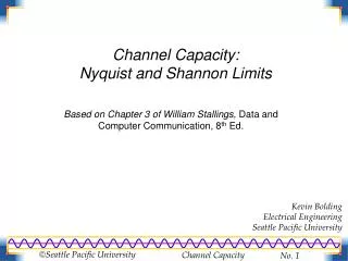
Channel Capacity: Nyquist and Shannon Limits. Based on Chapter 3 of William Stallings, Data and Computer Communication, 8 th Ed. Kevin Bolding Electrical Engineering Seattle Pacific University. Find the highest data rate possible for a given bandwidth, B Binary data (two states)

E N D
Channel Capacity:Nyquist and Shannon Limits Based on Chapter 3 of William Stallings, Data and Computer Communication, 8th Ed. Kevin BoldingElectrical EngineeringSeattle Pacific University
Find the highest data rate possible for a given bandwidth, B Binary data (two states) Zero noise on channel 0 1 0 1 0 0 0 1 0 1 1 0 1 0 0 Nyquist Limit on Bandwidth Example shown with bandfrom 0 Hz to B Hz (Bandwidth B)Maximum frequency is B Hz Period = 1/B • Nyquist: Max data rate is 2B (assuming two signal levels) • Two signal events per cycle
If each signal point can be more than two states, we can have a higher data rate M states gives log2M bits per signal point 00 10 00 11 00 00 00 11 01 10 10 01 00 00 11 Nyquist Limit on Bandwidth (general) Period = 1/B 4 signal levels: 2 bits/signal • General Nyquist: Max data rate is 2B log2M • M signal levels, 2 signals per cycle
4 levels - noise corrupts data 2 levels - better margins Practical Limits • Nyquist: Limit based on the number of signal levels and bandwidth • Clever engineer: Use a huge number of signal levels and transmit at an arbitrarily large data rate • The enemy: Noise • As the number of signal levels grows, the differences between levels becomes very small • Noise has an easier time corrupting bits
Characterizing Noise • Noise is only a problem when it corrupts data • Important characteristic is its size relative to the minimum signal information • Signal-to-Noise Ratio • SNR = signal power / noise power • SNR(dB) = 10 log10(S/N) • Shannon’s Formula for maximum capacity in bps • C = B log2(1 + SNR) • Capacity can be increased by: • Increasing Bandwidth • Increasing SNR (capacity is linear in SNR(dB) ) SNR in linear form Warning: Assumes uniform (white) noise!
From Nyquist: From Shannon: Equating: or SNR is the S/N ratio needed tosupport the M signal levels M is the number of levelsneeded to meet Shannon Limit Shannon meets Nyquist Example: To support 16 levels (4 bits), we need a SNR of 255 (24 dB) Example: To achieve Shannon limit with SNR of 30dB, we need 32 levels
0 1 0 1 0 0 0 1 0 1 1 0 1 0 0 Achieving the Nyquist Limit • The Nyquist Limit requires two signaling events per Hertz • C=2B log2M • This must be achieved using waveforms with frequency components <= B Period = 1/B “Corners” require higher-frequency components • We need a way to represent a ‘1’ with a pulse that has no components greater than B • Must be able to overlap two pulses per Hertz without loss of information
1 0.8 0.6 0.4 0.2 0 -0.2 -0.4 -5 -4 -3 -2 -1 0 1 2 3 4 5 1 0.8 0.6 0.4 0.2 0 -0.2 -0.4 -5 -4 -3 -2 -1 0 1 2 3 4 5 1.5 0 0 1 1 0 0 0 0 0 0 0 0 1 1 1 1 0 0 1 1 0 0 0 0 1 1 1 1 1 1 0 0 0 0 1 1 0 0 1 0.5 0 -0.5 -5 -4 -3 -2 -1 0 1 2 3 4 5 Sinc (Nyquist) Pulses • The Sinc Pulse is defined as sin(x)/x • Sinc pulse at frequency f requires bandwidth f • sin(x 2f)/(x 2f) • Note that the sinc pulse is zero at all multiples of 1/2f except for the singular pulse • Pulses can overlap as long as each one is centered on a multiple of 1/2f • When the pulses are summed, checking the waveform at each multiple of 1/2f gives the orignal data