Download
1 / 46
460 likes | 620 Vues
LHC Transverse feedback. W. H ö fle , D. Valuch Special thanks to: E. Montesinos , G. Cipolla , F. Killing, F. Dubouchet , A. Pashnin , M. Jaussi , V. Zhabitsky , B. Lojko , V. Kain , D. Jacquet , N. Mounet , B. Salvant , S. Redaelli , M. Zerlauth , R. Leszko.

E N D
LHC Transverse feedback W. Höfle, D. Valuch Special thanks to: E. Montesinos, G. Cipolla, F. Killing, F. Dubouchet, A. Pashnin, M. Jaussi, V. Zhabitsky, B. Lojko, V. Kain, D. Jacquet, N. Mounet, B. Salvant, S. Redaelli, M. Zerlauth, R. Leszko
The transverse damper in general • The transverse damper is a feedback system: it measures the bunch oscillations and damps them by fast electrostatic kickers • Key elements: • Beam position monitor(s) • Signal processing system • Power amplifiers • Electrostatic kickers Tbeam • Key parameters: • Feedback loop gain, phase and delay • Kick strength • Bandwidth Tsignal
Available PM data • Beam Position module • Last 73 turns, Bunch by bunch data • Raw Sum and Delta I-Q data for expert diagnostic • Digital Signal Processing Unit (DSPU) • Last 73 turns, Bunch by bunch data • 2x “Serdes data”: Normalized, intensity independent bunch position (at Q7 and Q9) • 2x “Notch” actual bunch motion at pickups in Q7 and Q9 after processing • “Bunch masking” total correction kick calculated by the ADT best signal for user to observe the potential instability • “DAC output”: pre-distorted signal sent to the power system, including cleaning/blowup pulses
Bunch by bunch observationpost mortem data Beam Position module Sent to the post mortem database Digital Signal Processing Unit Multiturn application gets this buffer Injection oscillations fixed display
Status of the post mortem data • PM data are being sent to the PM database since mid 2011 • User interface available since 2012 (thanks to RafalLeszko & Markus Zerlauth)
Available PM data Signal selection and placement “Serdes CH1” (normalized bunch position) “Bunch masking” (correction kick)
Available PM data Last turn Dashed lines – revolution frequency marker After-dump transient (3-5 turns)
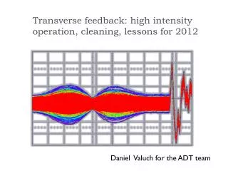
PM data example – dump fill #2668 Instability within the train End of train unstable Abort gap Note: the Y scale is in artificial units, not microns!
BBQ “Instability trigger” • BBQ can freeze the ADT observation memory if an instability develops • Software packet, under commissioning • Data acquisition controlled by the “multi-turn” application • User can select 1, 2, 4, 8 or all bunches to record • 1 for 262144 turns, 2 for 131072 turns, 4 for 65536 turns, 8 for 32768 turns or all for 73 turns • When an instability develops the buffer is frozen and data saved automatically for offline analysis
BBQ “Instability trigger” Manual acquisition BBQ trigger Acquisition synchronized by timing
Gain settings in collisions double w.r.t. last year
Gain settings in collisions • Concept of the Normalized gain • Parameter independent of the optics and hardware performance • Injection - High gain (0.25), damping times 8-15 turns • Prepare for ramp, low gain (0.02H/0.04V) • Kept low through the ramp (0.02 H/0.040.01 V) • Squeeze increase to double (0.04 H/0.02 V) • Physics (0.04H/V), double w.r.t. last year, damping time <50 turns
Frequency response ADT • Power amplifiers, -3 dB @ 1 MHz • Power amplifier phase response compensated by digital filter (flat) • Cable response compensated by analogue filter (flat) kick @ 10 MHz, 10% left measured on power amplifier (blue curve on kicker, green on anode of tetrode) LHC-PROJECT-REPORT-1148
Frequency response ADT • Power amplifier without phase compensation approximately e-(t-tg)/t1 for t>tg B. Lojko
Frequency response ADT • Power amplifier phase response compensated by digital filter SYMMETRIC! i.e. equal treatment of bunches on both sides of the train approximately e-|t-tg|/t2 B. Lojko
Frequency response/damping time • Available kick strength for trains of different length (“injection oscillation” type damping) 1250ns 625ns 150ns 50ns 25ns
Frequency response/damping time • Injection oscillations, 2nd injection of the fill 2676
Frequency response/damping time • Damping time for individual bunches within the 144b train. Injection oscillation fill 2676, 2nd injection New injection 144b 12b already circulating
Frequency response/damping time • Damping of individual bunches in case they become unstable however still follows the system frequency response: • -3 dB point at 1 MHz • i.e. 10% strength available at 10MHz if two adjacent bunches oscillate in anti-phase
Damping of single bunch instabilities • Impulse response of damper spreads oscillation to adjacent bunches • Simulation with simplified damper model (no delays, ideal system) • Feedback gain 0.05 (40 turns damping time) as in horizontal plane for beam 1 in Physics • Train of 48 bunches with random initial condition (bunch-by-bunch amplitude, phase)
Damping of single bunch instabilities • Case 1: • only one bunch is unstable • center of train is worse than edge ! • Edges symmetric (no preference for trailing edge), due to symmetric response
Damping of single bunch instabilities • Edge bunch unstable (bunch 1), 200 turns risetime under control
Damping of single bunch instabilities • Edge bunch unstable (bunch 48), 200 turns risetime under control • Due to symmetric impulse response same behavior as for case with bunch 1 unstable
Damping of single bunch instabilities • Edge Center of batch (bunch 24) is more critical than edge if one single bunch unstable. 300 turns risetime under control but 200 turns not!
Damping of single bunch instabilities • Case 2: All bunches unstable with same risetime and tune, but random initial condition harder to control with damper
Damping of single bunch instabilities • All bunches of train unstable • 300 turns risetime not under control, but increasing gain (40 20 turns) brings it under control
Damping of single bunch instabilities • All bunches of train unstable but slower risetime, lower gain (40 turns) • Risetimes of 1000 turns under control, but not 400 turns
Enhancement of the frequency response • The full power is needed only for efficient injection oscillation damping • An amplitude compensation filter is foreseen in the ADT’s digital signal processing • Once commissioned it should provide faster damping of high frequency modes • Potential drawback – increase of noise injected through the damper
Damping – variation with tune Circles of equal damping time Faster than 10 turns damping No active damping Design value 40 turns damping Contour lines at n/80 turns n=1…8 and 0.002 (1/t) Gain is the fraction of detected oscillation amplitude that is corrected in a single turn V. Zhabitsky et al.
Damping – variation with tune Tune variation ±0.02 no problem, at injection more critical ±0.01 Range of operation: 1: Injection (10 turns) 2: Prepare ramp, Ramp (100-200t) 3: Squeeze (100t) 4: Physics (50t) 2 3 1 4 Range of operation (gain) V. Zhabitsky et al.
Damping – variation with tune • Two modes of ADT operation available: • With phase shifter, using each pickup individually. Introducing additional 3.5 turn delay but better in terms of noise and reliability used since 2008 • Vector mode, direct combination of two pickups. No additional delay, worse in noise, more difficult to set-up not commissioned yet • Shall very high gain at 4 TeV be needed we may study use of the vector mode. Lower processing delay will provide wider tune acceptance range. All implications to the operation need to be carefully studied.
Damping – variation with tune • Xavier Buffat et al. 31.5.2012: • “The variation between bunches that they expect is 0.308 -> 0.322, so plus 0.002 and minus 0.012” • The normal center for the vertical plane at collision is 0.32, we can eventually better center our settings for this case
Measurements at 4 TeV, 31.5.2012 • Goal – verify the gain (damping time) of all systems at 4 TeV • 3 batches of 12 bunches, 1 batch non colliding • Used the Q kicker to excite whole batch
Measurements at 4 TeV, 31.5.2012 1st bunch of the non-colliding batch 7th bunch of the non-colliding batch
Measurements at 4 TeV, 31.5.2012 • Non-colliding bunches • Colliding bunches – damping time is in general slightly faster, analysis not finished
Normalized gain limits • As the beam gets stiffer with rising energy we have to increase the electronic gain to obtain constant effective gain (damping time) • Concept of the normalized gain makes this transparent to the user • Electronic gain is calculated using the desired damping time, energy and a calibration constant (measured at 450 GeV) • When the electronic gain reaches the available maximum it saturates and does not follow the energy anymore • Damping time then gradually increases with energy
Normalized gain limits • Updated limits from 31.5.2012. Maximum available normalized gain at 4 TeV • H.B1 0.05 • H.B2 0.0402 • V.B1 0.05 • V.B2 0.09 • Asking for higher normalized gain does not harm, but it does not have any effect either
ADT status in 2012 • Hor. B2 unit recabled during the winter TS visible improvement in terms of noise • An extra 1-turn delay was removed from the loops after the winter TS (5 vs. 4) improved tune range acceptance • Beam Position front ends properly set-up for 1.3-1.5-1.7e11 ppb operation during the start-up • The loop parameters were precisely set-up by measuring the beam transfer function during the start-up, both for injection and collision tunes
ADT status in 2012 • Comprehensible post mortem data available to all users • About half tetrodes replaced during the last TS back to the full design kick strength (>14000 filament hours) • Apparent 50-100% increase in strength w.r.t. start up 2012 • Conclusion: The ADT is at nominal design performance
ADT follow up in 2012 • Enhancement of the frequency response • Commission the digital pre-distortion filter to compensate for the low-pass character of the power amplifier to improve the single bunch damping capability • Preparation of massive re-cabling campaign during the LS1 • Preparation of new Beam Position front end for 7 TeV operation • Lower noise, increased observation capabilities
Summary • The ADT is believed to be in the best shape since the LHC start up in 2008 thanks to sufficient time provided for precise setting up and fine tuning • ADT post mortem: bunch-by-bunch data on dipolar motion, but no information on head tail motion (which could be important to have) • Dipole oscillations observed when the beam is lost seem to be small, 10s of um, machine seems to be very “intolerant” • BBQ triggered ADT acquisition becoming available, will provide additional diagnostics
Summary • Damper impulse response cannot be responsible for difference observed in fills with oscillations towards end of trains for symmetry reasons (supported by simulation) • Frequency characteristics of damper not well adapted to the type of single bunch instabilities observed now, some margin to improve with signal processing • Need to better understand instabilities to see if a different kind of kicker/power amplifier could help in the more distance future (after LS2)
Summary • Damping time measurements at 4 TeV showed expected design performance. • Shall a very high gain at 4 TeV be needed we may study use of the vector mode. Lower processing delay will provide wider tune acceptance range. All implications to the operation need to be carefully studied. • A systematic, automatic, performance analysis (fill by fill) using the observation or Timber data needs to be implemented to monitor the system parameters.
Thank you… • Many thanks to • The operations for the time given to set up the system • E. Montesinos, G. Cipolla, F. Killing and the power team for all the care about the power system • F. Dubouchet, A. Pashnin, M. Jaussi for their massive effort in the software domain • V. Zhabitsky and B. Lojko for calculations and simulations which allow us to improve the system