Innovative Measures and Parameters in Laser Welding: Analysis of Quality and Mechanisms
This paper explores favored parameters and innovative measures in laser welding, focusing on material aspects and process geometry. We analyze the impact of melt pool size, shape, and laser welding modes on the quality and performance of welds. Key mechanisms such as heat conduction, additional forces on flow, and keyhole dynamics are examined. The study also addresses issues with low boiling elements and spatter control while discussing the potential benefits of substituting zinc with aluminum. Our findings provide insights and guidelines for enhancing laser welding processes.

Innovative Measures and Parameters in Laser Welding: Analysis of Quality and Mechanisms
E N D
Presentation Transcript
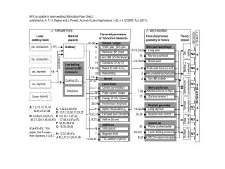
a PARAMETERS b MECHANISMS Favoured parameters or innovative measures Laser welding mode Material aspects Favoured process geometry or forces Theory: Impact d QUALITY g DECISION Sample / edges (to all) Wider gap / joint geo. pw, conduction 47c Ordinary C Melt pool size/shape 10,16,24,26 Long pool 3 Remove LBE (coat.,...) NO + 15 Narrow pool/weld 4 Less LBE (Zn-thickness) cw, conduction 10,16,24 Broad pool Substitute Zn by Al (all others) 41 Low boiling element (LBE) inclusions 17,31,45 React Zn with O,Cu,… H Thick melt front (no drill.) NO + pw, keyhole A 35 Hole drilling 2 No unstable/oscillat.pool 10, 37,43 Speed J No LBE-bubble Coating (Zn,...) B cw, keyhole Laser beam NO + Control cw-initiation 1 Melt pool forces Pollutions 7,39 Additional force on flow Surface Drag Vertical Momentum Boiling No tension force redirection concentration (reduced) boiling D Pulse param.,shape NO SPATTER (Laser hybrid) Surface tension ↑ 17 E Energy (P,I,E)(down) 29,34 Incline back (keyhole) Keyhole geometry A: 1,2,10,12,13,14, 16,20,21,27,28 NO + C: 4,22,23,25,47b F Optim. focal plane z0 18,22,28 Long keyhole D: 10,12,13,20,21,25,27 18,22,28 Elongate spot (tandem) 30,34 Keyhole rear control B: 3,4,6,22,23,25,31, 35-37,39,41,45,46,47b E: 4,5,10,11,27,32, 37,38,43,47a,47c 8,27 Add cw (to pw) NO + F: 32,34,38,47a Vapour jet Additions 40 Plume pushed aside G: 15,30,39,40 Side gas jet 47a,47b,47c: This paper, the 3 cases from Sections II A,B,C G 25,47c Lower boiling pressure Magnetic field H: 12,32,38,47a 7 NO + J: C,3,17,31,35,41,45 C,35 LBE(Zn)-vapour escape TIG-addition (hybrid) 13,33,45 BFC on spatter in laser welding (Bifurcation Flow Chart) published at: A. F. H. Kaplan and J. Powell, Journal of Laser Applications, v 23, n 3, 032005 (7 p) (2011).
a PARAMETERS b MECHANISMS Favoured parameters or innovative measures Laser welding mode Material aspects Favoured process geometry or forces Theory: Impact d QUALITY g DECISION Sample / edges (to all) Wider gap / joint geo. pw, conduction 47c Ordinary C Melt pool size/shape 10,16,24,26 Long pool 3 Remove LBE (coat.,...) NO + 15 Narrow pool/weld 4 Less LBE (Zn-thickness) cw, conduction 10,16,24 Broad pool Substitute Zn by Al (all others) 41 Low boiling element (LBE) inclusions 17,31,45 React Zn with O,Cu,… H Thick melt front (no drill.) NO + pw, keyhole A 35 Hole drilling 2 No unstable/oscillat.pool 10, 37,43 Speed J No LBE-bubble Coating (Zn,...) B cw, keyhole Laser beam NO + Control cw-initiation 1 Melt pool forces Surface Drag Vertical Momentum Boiling No tension force redirection concentration (reduced) boiling Pollutions 7,39 Additional force on flow D Pulse param.,shape NO SPATTER (Laser hybrid) Surface tension ↑ 17 E Energy (P,I,E)(down) 29,34 Incline back (keyhole) Keyhole geometry A: 1,2,10,12,13,14, 16,20,21,27,28 NO + C: 4,22,23,25,47b F Optim. focal plane z0 18,22,28 Long keyhole D: 10,12,13,20,21,25,27 18,22,28 Elongate spot (tandem) 30,34 Keyhole rear control B: 3,4,6,22,23,25,31, 35-37,39,41,45,46,47b E: 4,5,10,11,27,32, 37,38,43,47a,47c 8,27 Add cw (to pw) NO + F: 32,34,38,47a Vapour jet Additions 40 Plume pushed aside G: 15,30,39,40 Side gas jet 47a,47b,47c: This paper, the 3 cases from Sections II A,B,C G 25,47c Lower boiling pressure Magnetic field H: 12,32,38,47a 7 NO + J: C,3,17,31,35,41,45 C,35 LBE(Zn)-vapour escape TIG-addition (hybrid) 13,33,45