
Designing Combinatorial Circuits for Logical Operations
E N D
Presentation Transcript
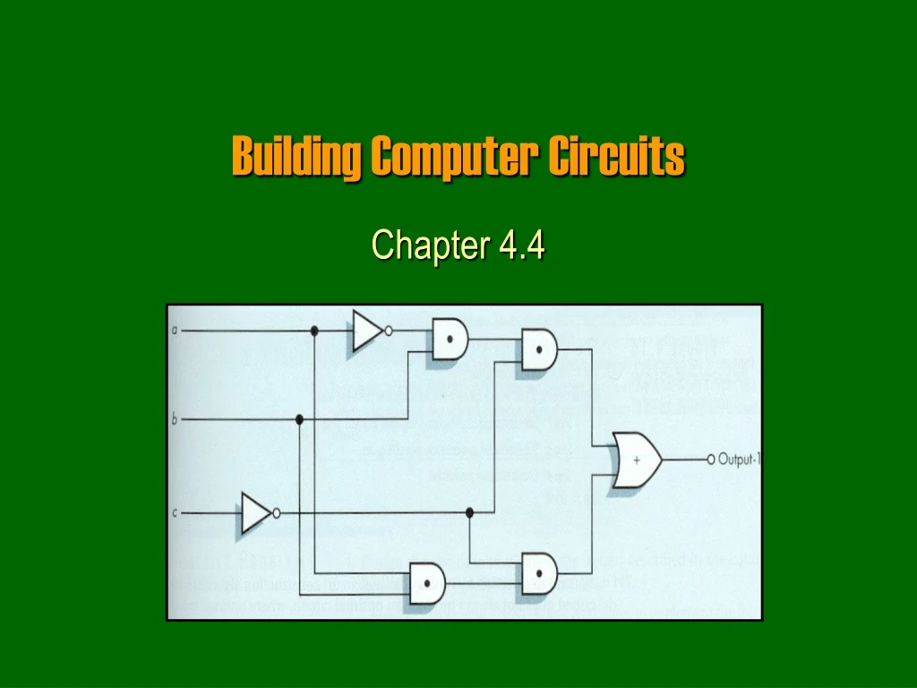
Building Computer Circuits Chapter 4.4
Purpose • We have looked at so far how to build logic gates from transistors. • Next we will look at how to build circuits from logic gates, for example: • A circuit to check if two numbers are equal. • A circuit to add two numbers. • Gates will become our new building blocks: • Human body: cells organs body • Computers: gates circuits computer (c) Yngvi Bjornsson
Circuit • A circuit is a collection of interconnected logic gates: • that transforms a set of binary inputs into a set of binary outputs, and • where the values of the outputs depend only on the current values of the inputs • These kind of circuits are more accurately calledcombinatorial circuits. (c) Yngvi Bjornsson
Circuit (external view) • A circuit can have any number of inputs and outputs: • Number of inputs and outputs can differ. • The inputs and outputs are either 0 or 1. (c) Yngvi Bjornsson
0 0 0 1 0 1 1 1 1 0 1 1 1 0 1 1 Circuit (external view cont.) • Output depends only on current input values • Each set of input always generates the same output. • Different sets of input can generate identical output. CIRCUIT OUTPUT INPUT (c) Yngvi Bjornsson
Circuit (internal view) • Circuits are build from interconnected AND, OR and NOT gates, in a way such that each input combination produces the desired output. (c) Yngvi Bjornsson
1 Example • What are the output values c and d given input values a=1, b=0? a 1 c 0 0 b d (c) Yngvi Bjornsson
Circuit Diagrams and Boolean Expressions • The diagrams we were looking at are called circuit diagrams. • Relationship between circuit diagrams and Boolean expr.: • Every Boolean expression can be represented pictorially as a circuit. • Every output in a circuit diagram can be written as a Boolean expression. • Example (output values c and d from previous diagram): • c = ( a OR b) • d = NOT ( (a OR b) AND (NOT b) ) (c) Yngvi Bjornsson
(a OR b) AND (NOT b) (NOT b) Circuits Diagram and Boolean Expressions • Deriving Boolean expressions for the output. a (a OR b) (a OR b) NOT ((a OR b) AND (NOT b)) b (c) Yngvi Bjornsson
a (a + b) (a + b) (a + b) · b (a + b) · b b b Circuits Diagram and Boolean Expressions • Remember, when writing Boolean expressions for circuit diagrams, we use a different notation! (c) Yngvi Bjornsson
a·b + a·b a a·b b Example • What Boolean expression describes the output? a a·b b (c) Yngvi Bjornsson
Constructing Circuits • How do we design and construct circuits? • We first have to know what we want the circuit to do! • This implies, that for all possible input combinations we must decide what the output should be. • Once we know that, there exists methods we can use to design the layout of the circuit. • We will look at one such method called, sum-of-products algorithm. (c) Yngvi Bjornsson
Sum-of-Products Algorithm Step 1: Truth Table Construction Repeat steps 2, 3 and 4 for each output column Step 2: Sub-expression construction using AND and NOT gates Step 3: Sub-expression combination using OR gates Step 4: Circuit Diagram Production Step 5: Combine Circuit Diagrams Step 6: Optimize Circuit (optional) Step 7: Stop (c) Yngvi Bjornsson
0 0 1 0 0 0 0 1 0 0 Circuit Step 1: Truth Table Construction • Decide what the circuit is supposed to do: • treat the circuit itself as a “black box” • only interested in input/output signals (c) Yngvi Bjornsson
3 inputs 23 = 8 possibilities Step 1 (cont.) • Write the desired output for all possible input combinations: (c) Yngvi Bjornsson
Case 1 Case 2 Step 2: Sub-expression Construction • For each output (separately): • Use AND and NOT gates to construct a sub-expression for rows where the output is 1 (c) Yngvi Bjornsson
a·b·c a·b·c Step 2 (cont.) • Look at the inputs, if the value is • 1 then use input as is in sub-expression, ( e.g. b ) • 0 then use input value complemented ( e.g. a ) • Why do it this way? • Each expression will evaluate to 1 for given input combination (row), but 0 for all other inputs! (c) Yngvi Bjornsson
( a·b·c ) + ( a·b·c ) Step 3: Sub-expression Combination • Use OR gates to combine the sub-expressions from previous step into one expression • This expression will evaluate to 1 for all input combinations that have 1 as output, but 0 for all the other input combinations (rows)! (c) Yngvi Bjornsson
( a·b·c ) + ( a·b·c ) a b c Step 4: Circuit Diagram Production • Construct a circuit diagram from the expression generated in previous step: (c) Yngvi Bjornsson
( a·b·c ) + ( a·b·c ) + ( a·b·c ) + ( a·b·c ) Repeat steps 2, 3, and 4 for each output • We need to repeat steps 2, 3, 4 for each output. • In our example, there is one more output: • Step2: Four sub-expressions, one for each row: • Step 3: Combine sub-expressions using + (OR): • Step 4: Draw circuit diagram a·b·c a·b·c a·b·c a·b·c • (see p. 694 in text-book) (c) Yngvi Bjornsson
a Circuit for Output 1 b Output 1 c Circuit for Output 2 Output 2 Combine Individual Circuits • Combine the circuits for each individual output into an one larger circuit. (c) Yngvi Bjornsson
Optimize the Circuit • A circuit build using this algorithm will generate the correct output, but it uses unnecessarily many gates • Why is that important? • Typically we need to optimize the circuit, by minimize the number of gates used. • An optimized circuit for the example would look like: (c) Yngvi Bjornsson
… = = = = Example 1: Compare-for-Equality Circuit (N-CE) • We want to build a circuit that checks if two numbers are the same? • The same number if and only if all corresponding bits are the identical. • First step is to build a circuit that compares two bits (can then use 16 of those to compare two 16-bit numbers!) (c) Yngvi Bjornsson
1-CE 0 0 1 Ex1 -- Step 1: Truth table construction • The circuit to compare two bits has: • two inputs (the value of the two bits) • one output (0 if the bits are different, 1 if the bits are same) • How does the truth-table look like? (c) Yngvi Bjornsson
a·b Example 1: Step 2 Construct sub-expressions • Construct a Boolean expression for each row in the table where the output is one: = = a·b (c) Yngvi Bjornsson
( a·b ) + ( a·b ) Example 1: Step 3 and 4 • Combine into one sub-expression using OR (+) • Draw a circuit diagram (c) Yngvi Bjornsson
Repeat for each output • Need to repeat step 2, 3, 4 for all outputs: • There is only one output, so we are done! • So our 1-bit compare circuit ( 1-CE ) looks like: • But we want to compare N-bit sized numbers? (c) Yngvi Bjornsson
N-bit compare a b 1 (c) Yngvi Bjornsson
Example 2: An Addition Circuit (N-add) • We want to build a circuit that adds two integers. • How do we add two binary numbers • the same way as decimal numbers (but different base) 1 1 1 a b + s 1 1 0 1 0 1 1 0 (c) Yngvi Bjornsson
0 carry = 1-ADD = carry 1 a = 1 = s 0 1 b = Example 2: 1-ADD • Let’s start by building a circuit that adds three bits (two bits + carry) • We can then use N of these 1-ADD circuits to add any two N-bit integers. (c) Yngvi Bjornsson
Ex2-- Step 1: Truth table construction (c) Yngvi Bjornsson
s = (a·b·c) + (a·b·c) + (a·b·c) + (a·b·c) a·b·c a·b·c a·b·c Example 2: Step 2-3 (output 1) • Construct a Boolean expression for each 1-row a·b·c • Combine into one Boolean expression (c) Yngvi Bjornsson
Example 2: Step 4 Circuit Diagram (output 1) (c) Yngvi Bjornsson
a·b·c a·b·c a·b·c s = ( a·b·c ) + ( a·b·c ) + ( a·b·c ) + ( a·b·c ) Example 2: Step 2-3-4 (output 2) • Step2 : Construct a Boolean expression for each 1-row a·b·c • Step 3: Combine into one Boolean expression • Step 4: Draw a circuit diagram (not shown) (c) Yngvi Bjornsson
Example 2: Combining output 1 and 2 circuits s carry (c) Yngvi Bjornsson
Example 2: N-ADD (c) Yngvi Bjornsson
Example 2: Optimize the circuit • Each 1-ADD circuit has 25 gates (47 transistors) • 16 AND gates ( x 2 transistors) • 6 OR games ( x 2 transistors) • 3 NOT gates ( x 1 transistors) • To add two 32-bits bits integers we need • 32 1-ADD circuits 32 * 25 = 800 gates 1504 transistors • Optimized 32-bits addition circuit in modern computers uses: 500-600 transistors • We will not learn how to optimize circuits in this course (c) Yngvi Bjornsson
Control Circuits Chapter 4.5
Control Circuits • So far we have seen two types of circuits: • Logical ( is a = b ?) • Arithmetic ( c = a + b) • Computers use many different logical (>, <, >=. <=, !=, …), and arithmetic (+,-,*,/) circuits. • There are also different kind of circuits that are essential for computers control circuits • We will look at two different kind of control circuits, multiplexors and decoders. (c) Yngvi Bjornsson
Multiplexor • A multiplexor circuit has: • 2N input lines (numbered 0, …, 2N-1) • 1 output line • N selector lines • The selector lines are used to choose which of the input signals becomes the output signal: • Selector lines interpreted as an N-bit integer • The signal on the input line with the corresponding number becomes the output signal. (c) Yngvi Bjornsson
Multiplexor (cont.) (c) Yngvi Bjornsson
Multiplexor 0 1 0 1 1 0 1 0 0 0 0 1 1 1 0 1 Multiplexor (cont.) 0 1 2 3 (c) Yngvi Bjornsson
Decoder • A decoder circuit has: • N input lines (numbered 0, 1, …., N-1) • 2N output line (numbered 0, 1, … 2N-1) • Works as follows: • The N input lines are interpreted as a N-bit integer value. • The output line corresponding to the integer value is set to 1, all other to 0 (c) Yngvi Bjornsson
Decoder (cont.) (c) Yngvi Bjornsson
Decoder (cont.) 0 Decoder 0 0 0 1 1 0 2 0 3 2 1 4 100 = 4 0 5 0 6 7 0 (c) Yngvi Bjornsson
Summary • We looked at how computers represent data: • Internal vs External Representation • Basic storage unit is a binary digit bit • Data is represented internally as binary data. • Use the binary number system. • We learned why computers use binary data: • Main reason is reliability • Electronic devices work best in bi-stable environment. (c) Yngvi Bjornsson
Summary (cont.) • We looked at the basic building blocks used in computers: • Binary Storage Device = Transistor • We saw how to build logic gates (AND, OR, NOT): • Transistors Gates • Boolean logic • We saw how to build circuits: • Gates Circuits • Looked at logical, arithmetic, and control circuits. (c) Yngvi Bjornsson
Summary (cont.) • Now that we have seen the basic building blocks (low-level view), in the next chapter we will look at the “big picture” (high-level view). • We will look at the basic architecture underlying design of all computers: • Look at higher level computer components, such as processors and memory. • Understand better how computers execute programs. (c) Yngvi Bjornsson