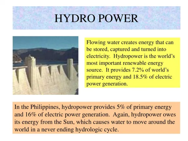
Hydro Forming
Hydro Forming. GUIDED BY ASST PROF: LINCE P SUNNY MECH DEPT MCET. SUBMITTED BY NIJIL ISMAIL S8 MECH 4241. INTRODUCTION Hydro Forming uses water pressure to form complex shapes from sheet or tube material. The pressure may go up about 60,000 psi depending on the component.

Hydro Forming
E N D
Presentation Transcript
Hydro Forming GUIDED BY ASST PROF: LINCE P SUNNY MECH DEPT MCET SUBMITTED BY NIJIL ISMAIL S8 MECH 4241
INTRODUCTION Hydro Forming uses water pressure to form complex shapes from sheet or tube material. The pressure may go up about 60,000 psi depending on the component. As the automobile industry strives to make car lighter, stronger and more fuel efficient, it will continue to drive hydro forming applications. Some automobile parts such as structural chassis, instrument panel beam, engine cradles and radiator closures are becoming standard hydro formed parts. The capability of hydro forming can be more fully used to create complicated parts. Using a single hydro formed item to replace several individual parts eliminate welding or hole punching, simplifies assembly and reduce inventory.
METHODS OF HYDRO FORMING There are two types of Hydro forming. 1. Tube Hydro forming 2. Sheet Hydro forming Sheet hydro forming converts the irregular shaped material into a finished anduniform thickness sheet. The tube hydro forming process is used to form parts in materials such as steel tubes and aluminum extrusions by applying hydraulic pressure.
1. TUBE HYDRO FORMING Straight, pre bent and or performed tubes are formed by internal water pressure with additional application of compressive mechanical forces. In this method the tube in placed in die and as press clamps the die valves, low pressure fluid is introduced into tube to pre form it. One the maximum clamping pressure in achieved, the fluid pressure inside the tube in increased so that tube bulges to take internal shape of the die. Simultaneously additional cylinders axially compress the tube to prevent thinning and brushing swing expansion
BENEFIT OF TUBE HYDROFORMING FOR AUTO MANUFACTURER • Increased strength to weight ratios • Improved stiffness torsion and bending rigidly • Improvement in NHV Factor • Incorporation of hole punching, slot making, embosses swing hydro forming process. • Reduction in number of manufacturing stages, hence tooling. • Reduction in welding, hence distortion and subsequent heat treatment. • Reduction in production cost • Reduced floor area
TUBE HYDRO FORMING PROCESS The hydro forming process varies slightly depending on the component, but here’s a general look at the overall procedure. • 1.First, a computer-controlled machine cuts a length of straight ‘metal tubing’, also called a blank, to the proper size and feeds it into a machine, where it is pre-bent into the approximate contour of the finished part. • 2. Next, the blank is inserted into the die, which is pumped full of highly pressurized water. • 3. The water fills the blank, which conforms to the die walls. The water shapes the blank into the desired form.
CONTINUE… 4. At the same time, the machine compresses the ends of the blank, which eliminates thin spots on the outer wall of the blank, and prevents wrinkling on the inner wall, as well. 5. The component is then removed from the hydro forming press, the ends are trimmed and mounting holes are pierced with lasers and cutting torches.
2. SHEET HYDRO FORMING Sheet hydro forming involves forming of sheet with application of fluid pressure. A sheet metal blank informed by hydraulic counter pressure generated by punch drawing sheet into pressurized water chambers. The water pressure effectively punches the sheet firmly against punch to form required shape. The major advantage of fluid forming is increased drawing ratio. The process take place in two stages performed during one press stroke. The sheet in preformed by applying low fluid pressure while it is in clamped firmly by a blank holder pressure. Preforming achieves on evenly distributed strengthening in the component center. In next step fluid pressure in gradually increased and blank holder pressure in controlled relative to sheet reformation.
NEW CONCEPT IN SHEET HYDRO FORMING DOUBLE SHEET HYDRO FORMING Structural component with closed components are formed by this process. Some advantages of this process are:- • Integration of more parts, further reduction of components & thus steps. • Stiffness increase and reduction in overall spring back due to closed box section & continuous weld section. • A complete component is made in one single hydroforming step, with only top and bottom die .
HYDRO FORMING PROCESS CONTROL A typical hydro forming system would include a press capable of developing necessary forces to clamp the die valves together when internal pressure acts on fluid; a high pressure water system to intensify water pressure for forming component, looking including aerial cylinder and punches, depending on component and a control system for process monitoring. Since the entire process of operation takes place inside a closed die, one cannot see what actually happens during forming. Therefore the controller plays a vital role in displaying, monitoring and controlling the different parameters of forming in real time.
Fig: Schematic Diagram of Tube Hydro forming and Process Control
ADDITIONAL HYDRO FORMING APPLICATIONS 1.HYDRO PATH WORK OR HYDRO FORMED TAILORED BLANK By this method, the need for additional forming / joining operation in avoided. It is used in areas where sound insulation and vibration damping is required & where high degree of energy absorption during crash in needed. The additional or path sheet could be of same or different material or different thickness from parent material.
2. HYDRO JOINING Usually after hydro forming, additional joining operations are required to form assemblies. To reduce manufacturing time and number of process steps, joining operation are being integrated into hydro forming process. This also reduces tool cost. Two approaches to hydro joining are punch riveting hydro clinching. In punch riveting, pressurized fluid acts on one sheet while a moving punch acts on other sheets from opposite sheet. Punch is moved against rivet and under the fluid counter pressure; it spreads to form a solid, visually attractive joint. In hydro clinching, high pressure fluid action the punch. The prescribed fluid presses the material to be hydro formed part through a note in sheet to be joined.
ADVANTAGES • Hydroforming draws material into the mold • Part consolidation • Weight reduction through more efficient section design and tailoring of the wall thickness • Improved structural strength and stiffness • Lower tooling cost due to fewer parts • Fewer secondary operations (no welding of sections required and holes may be punched during hydroforming) • Tight dimensional tolerances and low spring back • Reduced scrap
DISADVANTAGES • Slow cycle time • Expensive equipment and lack of extensive knowledge base for process and tool design • Requires new welding techniques for assembly.
APPLICATIONS 1. Body shell 2. Driving shaft 3. Assembled camshaft 4. Exhaust systems 5. Engine cooling system 6. Radiator frame 7. Safety requirements 8. Engine bearer 9. Integral member 10. Cross member 11. Frame structure parts 12. Axle elements
MATERIALS • Steel (mild and harder steels) • Stainless Steel • Aluminum alloys • Research continues to expand the capabilities of the hydroforming process
6. CONCLUSION During the last 12 years, general awareness of hydro forming has grown steadily. Although interest in hydro forming is wide ranging, the vast majority of application are in automobile industry. Hydro Forming is not solution for manufacturing all automotive parts. The benefits of automotive light weight resin and weight reduction achieved by hydro forming can be measured in kilogram. It cannot be applied to every components, one has to study inability of hydro forming the part and the economic and technical payback. Just like transistor revolutionized the electronic industry, hydro forming has taken the vehicle manufacturing industry a step up to evolutionary ladder, allowing auto component for vehicle. Although hydro forming has not taken off rapidly as it should have, is only matter on time before this technology is absorbed in the industry.