Thermal Treatment/Disposal: Incineration
Thermal Treatment/Disposal: Incineration. Chapter 12. Activity. Why use incineration? What are the drawbacks?. Regulations. Historical perspective HW incinerators vs. cement kilns and light aggregate kilns and industrial boilers and furnaces. General Schematic. Rotary kiln Fixed hearth

Thermal Treatment/Disposal: Incineration
E N D
Presentation Transcript
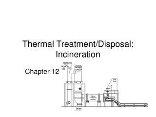
Thermal Treatment/Disposal: Incineration Chapter 12
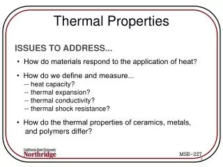
Activity • Why use incineration? • What are the drawbacks?
Regulations • Historical perspective • HW incinerators vs. cement kilns and light aggregate kilns and industrial boilers and furnaces
Rotary kiln Fixed hearth Liquid injection Cement and lime kilns Fluidized bed Boiler systems Oxygen enriched Infrared Fume Multiple chamber Multiple hearth Cyclonic Auger combustor Two-stage (starved air) Catalytic Molten salt Types of Incinerators
Other Thermal Processes • Plasma arc pyrolysis • Microwave discharge • Advanced electrical reactor • In situ vitrification • Wet air oxidation • Supercritical water oxidation • Calcination • Thermal desorption
Grate Open “rack” Stationary or moving Air circulation Large and irregular wastes Hearth Solid “plate” Variety of waste Suspension Sand or alumina bed fluidized with air Relatively uniform feed size Classifications of Incinerators
Typical Process Flow Diagram Waste Storage Pre-processing/blending Pollution Control Incineration Flue Gas Ash Stabilization Effluent Landfill POTW
Combustion Requirements 3 T’s + Excess O2
Typical Excess Air Reactions CHCl+ O2 + N2 CO2 + H2O + HCl + O2 + N2 + heat
Flue Gas Quench • Cool to: • 500 - 700oF for spray dryer • 180oF for low-temperature equipment • Air or water • Concurrent or counter-current flow
Air Pollution Control • Pollution: • Particulates (including 10 priority metals) • Acid gases • Systems • Wet • Dry
Trial Burn Test incinerator • Principal organic hazardous constituents (POHCs) destruction and removal efficiencies (DREs) • HCl • Particulates • CO • Metals • Dioxin and furans
POHC DRE At least 99.99% on all selected POHCs during trial burn
HCl Emissions Emission no greater than larger of 4 lb/h or 1% of HCl in stack gas
Particulate Emissions At most 0.08 grains/dscf corrected to 7% O2 or 180 mg/dscm corrected to 7% O2
Emissions Example Example 12-2 (p. 746) Does incinerator performance meet requirements?
CO Emissions 100 ppm by volume as a 60-minute rolling average corrected to 7% O2 on a dry basis
CO and Particulate Example Example 12-11 (p. 804)
Combustion Efficiency At least 99.99%
Dioxin and Furan Emissions 0.4 ng/dscm or 0.0001%
PCBs At least 99.9999% DRE for liquid Dwell time of 2 s at 1200 100oC and 3% EA in stack gas OR Dwell time of 1.5 s at 1600 100oC and 2% EA in stack gas
Design Example 12-7 (p. 765)