Chapter Seven Descriptive Geometry: Auxiliary Views
Chapter Seven Descriptive Geometry: Auxiliary Views. Purpose. This chapter provides an overview of how to: understand the spatial relationship between points, lines, plane figures and solids when these features are represented in orthogonal projection

Chapter Seven Descriptive Geometry: Auxiliary Views
E N D
Presentation Transcript
Chapter Seven Descriptive Geometry: Auxiliary Views
Purpose This chapter provides an overview of how to: • understand the spatial relationship between points, lines, plane figures and solids when these features are represented in orthogonal projection • draw primary and secondary auxiliary views • draw full and partial auxiliary views • Determine the true shape of an inclined or oblique surface, using auxiliary views.
Descriptive geometry • The projections of a point onto the principle planes are also points, identical to the original point; however, its position may vary in respect to the reference plane (p.182). • Figure 7.1, p.182, shows three cases of the projection of a point.
Descriptive geometry • If a plotted line is parallel to any of the principle planes of projection, its true length and angle of inclination to the horizontal and vertical planes can be found by projection onto one or two of the principle planes of projection. • A number of possible line positions relative to the principle planes of projection are shown both pictorially and orthogonally in Figures 7.2 (a)–(f), p.183.
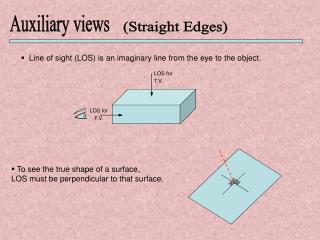
Descriptive geometry • If the inclination of the surface to the horizontal or vertical planes is known, we can proceed to find the true shape of the surface using either of the two methods shown in Figure 7.3, p.184. • Figure 7.3(a) shows an object inside the viewing box with its front and top views projected onto the horizontal and vertical planes respectively, as well as the true-shape view of the inclined edges projected onto an auxiliary inclined plane (AIP), which is parallel to the plane of the two inclined edges. The right-hand view illustrates how the true shape can be constructed using projectors and fold lines.
Descriptive geometry • Figure 7.3(b) shows an object within the viewing box and having a vertically inclined surface which is not parallel to any of the main reference planes. In order to project the true shape of the vertically inclined surface, an auxiliary vertical plane is placed in front of and parallel to it. The pictorial view shows how the three principle views and the true shape are projected from the solid and how they relate to each other.
True length and inclination of lines • Two right-angled triangles (ABD and ABC) are formed when a line situated in space in the third dihedral angle (Figure 7.4, p.185) constitutes a common hypotenuse and: • BD is drawn parallel to the front view, and is therefore equal in length to it; it also makes an angle β with AB. • AC is drawn parallel to the top view, and therefore is equal in length to it; it makes an angle α with AB.
True length and inclination of lines There are seven important facts about a line and its position in the dihedral angle which enable it to be fully described in orthogonal projection: • Its true length • Its front view length • Its top view length • Its angle of inclination to the horizontal plane (α) • Its angle of inclination to the vertical plane (β) • The vertical difference in height of the ends of the line below the horizontal plane • The horizontal difference in the distances of the ends of the line from the vertical plane
True length and inclination of lines • A knowledge of the composition of the two right-angled triangles ABC and ABD will enable all of the seven facts about the line to be solved. • If you can remember and understand the origin of these two triangles, and be able to construct them, there will be very little difficulty in solving problems involving true length and inclinations of lines. Refer to Figure 7.5, p.185.
Methods of determining true length • Six (6) methods of determining true length and two (2) worked examples are provided on pages 186–188.Examples are below.
Auxiliary orthogonal views • Auxiliary view – when a true shape view can only be obtained by projecting it onto an auxiliary plane parallel to the face. • Two types of auxiliary views: • Primary • Secondary
Primary auxiliary views • Primary view – the auxiliary plane is inclined to four of the six principal planes of projection and is square with the other two; see Figures 7.9(a), (b) and (c), p.190. • It will be noticed in each of the three figures that measurements of length are projected from the edge view of the inclined irregular face. Measurements of width required to complete the auxiliary view are transferred from the other principal view, and are normally measured from a reference plane (RP).
Primary auxiliary views • Partial auxiliary views – sometimes it is advantageous to only draw the irregular face and not a complete auxiliary view as it saves drawing time, simplifies the drawing and makes it easier to read. • Figure 7.10(a), p.191, illustrates a complete auxiliary view, part of which is completely distorted due to the angle of viewing and is of little descriptive value. Figure 7.10(b) shows the use of the partial auxiliary view which omits the distorted portion.
Primary auxiliary views • Auxiliary views are commonly projected perpendicularly from the inclined face to obtain true shape (Figure 7.11, p.191); however, for greater convenience or clarity (dimensioning or layout on a drawing sheet) the full or partial auxiliary view may be removed from its normal position without changing its orientation. • The word ‘view’ followed by a direction indicator, such as ‘A’, should be used to identify the view, and the direction of viewing should be indicated by an arrow together with indicator ‘A’.
Primary auxiliary views • If the removed view also needs to be re-oriented, the number of degrees of rotation and its direction must be stated (Figure 7.11(c)). • Removed views drawn to a larger scale are labelled with the word ‘detail’ followed by a letter as well as an indication of the scale used (Figure 7.12). The portion of the actual view removed is enclosed in a circle or a rectangle drawn with a thin type B line. • Example of primary auxiliary view: Figure 7.13, p. 193. • Example of complex primary auxiliary view: Figure 7.14, p.194.
Secondary auxiliary views • Secondary auxiliary view–sometimes an object will have a face inclined to all principal planes of projection. It is then necessary to draw first a primary auxiliary view to obtain an edge view of the inclined face, and then a secondary auxiliary view to give the true shape; refer to Figure 7.15, p.195. • Figure 7.16(b) (p.196) illustrates the application of a secondary auxiliary view to enable the construction of an oblique face of a component on the normal front and top views. Figure 7.16(a) is a pictorial view of the component.
General rules • Rule 1 An auxiliary view is normally used to detail an inclined face of an object which would be distorted on a principal orthogonal view. • Rule 2 An auxiliary view is projected at right angles to the edge view of the inclined face contained in a principal orthogonal view.
General rules • Rule 3 The auxiliary view is placed on the same side of the normal view as the position of viewing.
Summary To be able to draw an auxiliary view successfully, obtaining true length, angle and shape, one must form a mental picture of how the object will look from the direction of viewing. To achieve this you must have a clear understanding of how objects are projected from the horizontal and vertical planes when they are inclined at angles to the planes.