Download
1 / 6
60 likes | 184 Vues
This comprehensive guide outlines the step-by-step procedure for preparing and assembling trigger cables, focusing on stripping the cable, applying thermal sleeves, and soldering connections. Key steps include carefully managing shielded wires, ensuring proper lengths for each pair, and securing ground wires. It emphasizes the removal of paper and aluminum shields, the precise application of thermal shrink-wrap, and proper identification of each twisted pair. This process ultimately ensures a robust and effective signal transmission.

E N D
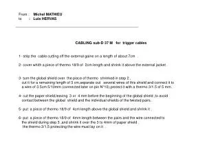
From : Michel MATHIEU to : Luis HERVAS CABLING sub-D 37 M for trigger cables 1- strip the cable cutting off the external gaine on a length of about 7cm . 2- cover whith a piece of thermo 18/9 of 2cm length and shrink it above the external jacket . 3- turn the global shield over the piece of thermo shrinked in step 2 , cut it for a remaining length of 3 cm,separate out several wires of this shield and connect it to a wire of 3.5cm 5/10mm (connected later on pin N°10),protect it with a thermo 3/1.5 of 5 mm. 4- cut the paper shield,leaving 3 or 4 mm before the beginning of the global shield ,to avoid contact between the global shield and the individual shields of the twisted pairs. 5- put a piece of thermo 18/9 of 4cm length above the global shield and shrink it . 6- put a piece of thermo 18/9 of 4mm length between the pairs and the wire connected to the shield during step 3 ,and shrink it over the 3 to 4mm of paper shield . the thermo 3/1.5 protecting the wire must lay on it .
3 4 8 6 2 5
7- for each of the 16 pairs : - cut off the aluminium shielding with a thin pair of pliers at about 6 to 10mm from the sleeve layed in step 6 ,just make a little gash finishing by hand .(A) - cut off the paper shield of the pair as shorter as possible . - put the transparent 0.8mm sleeve over the ground wire(length 5.5cm) maintaining it by turning the wire backward.(8) - put on a sleeve of thermo 3/1.5 of 5 mm at the junction of the 3 wires and the shielding , the thin transparent sleeve being inserted under the aluminium shield .shrink the thermo covering the 2 parts.(B) - cut each pair ,stripping 3mm and tinning so that the max length of each pair measured from main shield is not larger than : (C) length pair 42mm 0, 1, 14, 15 40mm 2, 3, 12, 13 38mm 4, 5, 10, 11 36mm 6, 7, 8, 9 - each pair must be identified with the noch connected at the other end. - soldering each pair maintaining the wires twisted ,put a sleeve 3/1.5 of 5mm on each wire , starting in the middle of the connector . remind to group the ground wires by 4 . - soldering the wire of the global shield on pin 10 .(put a sleeve 3/1.5 ) (D)
7B 7 D Max 7 C 7 A
8- finishing by the ground wires in 1 ,20, 19 et 37 because of the weakness , probably it will be necessary to adjust the lengths of the transparent sleeves of .8mm . 9- assembling of the case ,some glue is necessary at the end of the 2 part of the case ,install the 2 secure screw at the same time with the vise check the insulation between the case and pins 10,1,19,20,37 . 8
10- close the case with screw and bolt . thermo sleeve 18/9 : 6.5cm by connector thermo sleeve 3/1.5 : 54 x 5mm = 26 cm by connector transparente sleeve dia 0.8mm : 16 x 5cm = 80 cm by connector neopren glue fil 5/10 mm : 4.5 cm by connector 9 9