Download
1 / 17
170 likes | 315 Vues
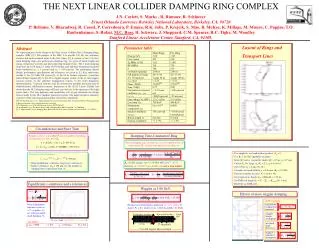
Linear Collider Damping Ring and Central Integration. Norbert Collomb. N. Walker, E. Paterson, V Kuchler, J. A. Osbourne , T. Lackowski, A. Wolski, S. Guiducci, N. Solyak,…. Acknowledgements to:. 30/09/2009. Central Integration.

E N D
Linear Collider Damping Ring and Central Integration Norbert Collomb N. Walker, E. Paterson, V Kuchler, J. A. Osbourne, T. Lackowski, A. Wolski, S. Guiducci, N. Solyak,… Acknowledgements to: 30/09/2009
Central Integration The Damping Rings are almost an independent system of the ILC. The race track layout permits it to be positioned almost anywhere relative to the other systems. One main constraint determines the position however; cost/performance ratio. Therefore, tunnels need to be as short as practically possible with the maximum beam dynamics achievable. It is reasonably obvious to have the Damping Rings in one tunnel with the centre plane (X-Y) coinciding with the I.P. Taking a global view then raises the question: Which side of the main beams? Norbert Collomb 30/09/2009
‘U.K.’ AD&I machine layout (I.P. at Z:0, X:0) Central Integration – AD&I Positron Main Dump Electron Main Dump N.Collomb
‘CERN/FNAL’ AD&I machine layout (I.P. at Z:0, X:0) Central Integration – AD&I Question: Which side? Answer: Opposite Main Dumps Positron Main Dump Electron Main Dump N.Collomb
Central Integration – AD&I For the first time; Lattice Design components and CF&S 3D CAD combined. Damping Ring Racetrack RTML Tunnels e- Side (e+ Source) Service Tunnel e+ Side (e- Source) Target Hall Immediate identification of clashes, Lattice Damping Ring Injection and Extraction off-set too small. N.Collomb
Central Integration – AD&I e- side Heading towards I.P. Note; 4 shafts, 3 caverns Positron Source e+ side Heading towards I.P. Target Hall for ‘Push-Pull’ detector I.P. e- Main Dump (after collision) Proposed service tunnel N.Collomb
Central Integration – AD&I First Value Engineered suggestion e- Side (e+ Source) Eliminate separate Damping Ring Building and associated shaft. Combine access to Target Hall and Damping Ring. Close liaison between Work Groups permit improvement suggestions like this early on. e+ Side (e- Source) Let’s have a look inside the tunnel N.Collomb
Electron Beam direction Positron Beam direction Central Integration – AD&I Electron RTML (coming from DR) Transfer Tunnel branch I.P. (down here somewhere) Positron Transfer Line heading into DR Positron Main Dump line (after collision) BDS (e- side) Heading towards I.P. N.Collomb
Central Integration – AD&I Summary There are a number of Beam lines which have been omitted due to time constraints. Some improvements are being incorporated already. Further value engineering opportunities are being identified. BDS lattice design is being optimised (as we speak). Updates of CAD (2D and 3D) are made as quickly as possible after new info is available. Note, this is a first step in the Overall Layout integration and there are many risk highlights. It is felt that huge progress has been made and continues to do so. There seems to be a light at the end of the tunnel!! I’d like to go as far as saying that a big proportion of the fluidity of the machine has been solidified. Don’t forget that some areas are best guesstimates and need to be confirmed by physicists. I’d like to take the opportunity and thank everyone for their collaboration and excellent communication to get to this stage. Damping Ring specific progress on next slides. N.Collomb
Damping Ring progress Where are we now? We now have 2 complete lattice designs; DC04 for the 6.4km Damping Ring solution (frozen) and DSB3_2 for the 3.2km Damping Ring solution (the latter needs to be looked at in more detail when time permits). Regardless of the circumference, the majority of mechanical engineering support structure solutions are applicable to both (in the broadest generic term). The vacuum system design (chamber, pumping and protection) differs; especially in the Arc Cells where it remains an engineering challenge. However, the principles adopted for the 6.4km design may be applied. To recap on the work done to date and outline further actions the following slides will aid. Damping Rings have beams going in opposite direction. Beam separation aimed at 1.3m (more on this later) with Electron Ring (1.1m above floor) below Positron Ring. Damping Ring centre in line with I.P. (off-set to be defined and agreed with CF&S and RTML Work Group). N.Collomb
Damping Ring progress DC04 Overall Layout (simplified) Positron Wiggler Section Electron Wiggler Section Electron RF Section Positron RF Section Quick print layout (Positron Ring off-set for clarity). e+ injection e- extraction e- injection e+ extraction N.Collomb
Damping Ring progress DC04 Overall Layout (AutoCAD) from DC04 Lattice Positron Wiggler section e+ e- Electron Wiggler section Damping Rings exactly on top of each other Positron Wiggler Section Electron Wiggler Section Electron RF section Positron RF section Electron RF Section Centre of Damping Rings in line with I.P. (symmetry) Positron RF Section e+ Injection & e- Extraction e- Injection & e+ Extraction I.P N.Collomb
Damping Ring progress DC04 ARC Cells We have broken the Damping Rings into sections: Arc Cells; Design work complete for the 6.4km option, bottom-up costing nearing completion. Towards centre of DR Ante-ChamberedVessel e- Gate Valves (1 per 5 Arc Cells) No changes to Arc Cell design since Chicago meeting in 2008. Positron Vessel Support Structures designed for 1.3m off-set and 1.1m from floor. (may change due to RF module size) Electron Vessel e+ Dipoles vertically aligned Gate Valves (1 per 5 Arc cells) N.Collomb
Damping Ring progress DC04 Wiggler Section 2. Wiggler section; work on vacuum system underway including chamber design (Maxim Korostelev’s presentation). Big thank you to Cornell and LBNL for their information on the CESR-TA wiggler design. Steering Magnet (could be eliminated by introducing a mover system for the Quad magnet) Quad Magnet Schematic Positron Wiggler BPM with Bellows arrangement Vacuum Vessel studies in progress. Looking at Cross section changes and its effects on Impedance, Beam Position monitoring, LET, e-cloud power deposition, photon absorption, vacuum etc. N.Collomb
Damping Ring progress Vanes in Ante-chamber (NEG coated) for power absorption. DC04 Wiggler Section ‘Wedge’ for ‘X’-section change Photon Absorber Flange Beam direction Beam direction Cooling channels Cooling channels BPM Flange Wiggler Vacuum Chamber without and with Flange Vacuum Vessel with Ante-chamber going through Steering and Quad magnet. BPM Flange Beam direction Circular vessel ‘X-section’ to permit the use of existing Arc Cell BPM Design. BPM Flange Beam direction N.Collomb
Damping Ring progress DC04 RF Section 3. RF section; initial layout started (based on Cornell’s 500 mHzCryomodule). Vertical separation could work at 1.3m with e- beam at 1.1m off floor (as ML, Sources and BDS). Better to separate by 1.5m as tunnel may be 5.2m in diameter (CF&S to confirm). From RDR CF&S suggest 5200 mm Cornell 500mHz Cryomodule Assumed size of 650mHz Cryomodule (20% smaller?) e+ Quad Magnet e+ wiggler 1.3m 1.1m Cornell 500mHz Cryomodule e- Quad Magnet Assumed size of 650mHz Cryomodule (20% smaller?) e- wiggler Need to determine these dimensions N.Collomb
Damping Ring progress Summary The DC04 lattice takes into consideration space requirements for vacuum systems and associated components. The wiggler to wiggler distance has been updated accordingly = lattice frozen. Bottom up costing for the Arc Cells show that this can be a lengthy process. The advantage is that the estimate maybe within 10% of the real cost. Value engineering opportunities are being identified, i.e. keep the same BPM arrangement throughout. Intensive work should see the engineering design for the wiggler section approaching the same status as the Arc Cell design within the next 4 – 5 months. It is envisaged to continue the process on the RF section thereafter and where permitted concurrently. An initial look at the Injection and Extraction lattice indicates no major problems. The detail design for the Damping Rings is far ahead of other systems and some minor issues, i.e. beam separation, DR off-set from I.P. and Beam Transfer can be addressed easily. I’d like to thank everyone for their contributions to enable this progress and look forward to the next stage of the evolution. N.Collomb