Development and Application of SimPix: A Software Tool for MCC Testing and Simulation
This document outlines the development of SimPix, a C++ simulation tool designed for comprehensive testing of the MCC (Module Control Chip). Given the limitations of conventional testing methods, SimPix generates arbitrary inputs and analyzes the MCC's responses using advanced hardware tools. The modular and flexible architecture facilitates various testing scenarios and validations. Additionally, a scripting language is integrated for easier test vector creation, enhancing automation and efficiency in testing MCC functionalities. This tool is vital for validating designs, investigating bottlenecks, and post-production analysis.

Development and Application of SimPix: A Software Tool for MCC Testing and Simulation
E N D
Presentation Transcript
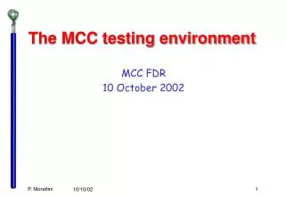
The MCC testing environment MCC FDR 10 October 2002 P. Morettini
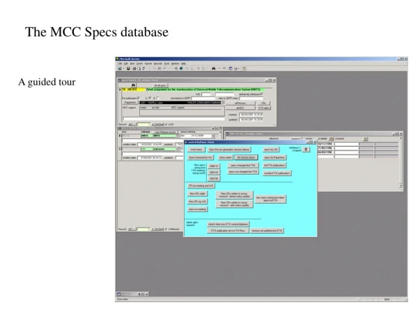
Introduction • Since the beginning of the MCC development it was clear that it was impossible to test all its functionalities using a pixel detector module. The typical rates one can obtain at a test beam or with a source are far from the design ones. Moreover, being impossible to control the input, its difficult to perform a detailed test of the chip response. • For this reason we developed a test strategy based on a software program (SimPix) being able to generate arbitrary input to the MCC and a set of hardware tools to send the input pattern to the MCC and read back the output for the analysis. MCC Verilog Model Design Specification SimPix MCC Detector Simulation P. Morettini
SimPix block diagram Detector response and LVL1 simulator FE behavioral simulation MCC behavioral simulation MCC input preparation MCC or Verilog model MCC command generator MCC output decoding Automatic analysis Clock Generator Time oriented database P. Morettini
SimPix implementation • SimPix is a C++ program running under Windows. It uses TCL/TK for the GUI. It’s easily portable to Unix/Linux. • Thanks to the Object Oriented design it’s highly modular and flexible. It’s easy to add new components or to replicate existing ones (we are considering to use it to study the Pixel ROD performance, and this will require the addition of a ROD simulation and the replication of the MCC and FE simulator). • The modular design extends inside the different components; so, for example, it’s possible to test two different implementation of the MCC event builder leaving the rest of the MCC model untouched. P. Morettini
SimPix functions • Pure simulation tool: the full Pixel DAQ chain is simulated to evaluate bottlenecks and inefficiencies. • Architecture robustness studies • DAQ impact on detector performance • Design validation: the software simulation is compared with the output of the Verilog model. • Implementation validation • Verilog code debugging • Chip test: the software simulation is compared with the output of a true MCC • Post-production tests • Debugging of anomalies P. Morettini
Standard SimPix operations • In the standard configuration SimPix compares the output of a true MCC or of a Verilog model with the output of a behavioral C++ MCC model. The input is taken from a Geant simulation and modified by a C++ FE model. Module selector C++ FE Model MCC Geant Module Hits Random Hits/Noise Generator Automatic Comparison C++ MCC Model P. Morettini
SimPix as a simulation tool • In pure simulation mode no external MCC is connected. The Noise Generator can be used to investigate the response of the system as a function of the occupancy of the pixel detector. Module selector C++ FE Model MCC Geant Module Hits Random Hits/Noise Generator Automatic Comparison C++ MCC Model P. Morettini
SimPix as a simulation tool • In general the Module Selector chooses one single module for the simulation. It can, however, loop over the entire Pixel Detector. In this case it is possible to save the output in the same format as the input simulation, to check the impact of the electronic chain on the physics performance of the detector. Module Selector C++ FE Model MCC Geant Module Hits Random Hits/Noise Generator Automatic Comparison C++ MCC Model Geant Ntuple P. Morettini
The SimPix scripting language • To simplify the writing of the MCC test vectors we implemented inside SimPix a scripting language. The language provides: • Support for all the MCC commands • Generation of Fe hits and EoE • Timing control on the DCI and DTI lines • Variable substitutions • Elementary flow control (loops) P. Morettini
The SimPix scripting language • In script mode, the FE model is bypassed, and the FE output is generated directly by the interpreter. Module selector C++ FE Model MCC Geant Module Hits Random Hits/Noise Generator Automatic Comparison Script Interpreter C++ MCC Model Script File P. Morettini
Output verification in script mode • The script commands • TRIGGER • 10 EVENT • HITS_EOE ffff 3 1 • END_EVENT • generate a TRIGGER command to the MCC and, after 10 clock cycles, a set of hits + EoE in all the FE (3 hits in average, with a spread of one hit). • The hits will be generated randomly, and the analysis module will check the presence of the generated hits in both the MCC outputs. FE mask Number of hits (mean and sigma) Delay P. Morettini
Support for FE and MCC configuration commands • The control and configuration lines (CCK, LD, DI, STR, STRO) are usually ignored by SimPix; in script mode however the MCC model provides the expected duration of CCK, LD, RSOb and STRO depending on the command issued and on the MCC register settings. The expected durations are then compared with the actual chip output. • The expected output of the MCC inspection commands (RD_REGISTER, RD_FIFO) can be specified in the script to allow automatic checking: • WR_REGISTER FEEN 0xfaff • RD_REGISTER FEEN 0xfaff Read register FEEN; the expected output is faff plus the header P. Morettini
Interface with the MCC Verilog Model • In order to check the MCC Verilog Model before submission we have interfaced it with SimPix. • The interface consists of a TCP connection between the PC running SimPix and the workstation running the Verilog simulation. In this way we avoid an excessive load of a single CPU and we do not force SimPix to run on the same architecture as Verilog. • SimPix activates the Verilog simulator on the remote machine, and opens the TCP connection. At every clock cycle it sends DCI, LVL1 and the 16 serial FE outputs. • The Verilog model replies with DTO, DTO2, LD, CCK, DI. • The two simulations run in parallel on the two machines. P. Morettini
Tests of the MCC-DSM Verilog model • The MCC-DSM Verilog behavioral model has been tested extensively with a set of test vectors generated with the SimPix scripting language. • The C++ MCC-DSM model included in SimPix has been tuned to reproduce the Verilog model behavior in a reliable way. • The SimPix automatic analysis module is used to compare the Verilog model output with the output of the behavioral C++ simulation. • Some of the vectors have been run also on the netlist. This type of run is very CPU demanding. P. Morettini
Verilog code validation with SimPix • The output of the Verilog model and of the C++ model are compared by the automatic analysis tool. At the beginning some adjustment is needed to equalize the detailed timing of the two models (and some small difference remains). Module selector C++ FE Model Verilog Model Geant Module Hits Random Hits/Noise Generator Automatic Comparison Script Interpreter C++ MCC Model Script File P. Morettini
MCC-DSM Test Vectors (I) • 1 - Read and Write operations on registers and FIFOs: • GlobalReset command test; • read and write operations on Receivers' FIFOs and PendingLevel1FIFO; • read and write operations on configuration registers. • 2 - Output line test: • 10101010... pattern output by setting CSR-OPAT. • 3 - Front-End configuration: • read and write operations using WriteFE and ReadFE; • single Front-End selection; • Front-End reset command. • 4 - Receiver test: • write operations using WriteReceiver; • event reconstruction in EventPlayback mode; • single Front-End selection. P. Morettini
MCC-DSM Test Vectors (II) • 5 - Full event reconstruction: • 40, 80, 160 Mbit/s output modes test; • TOT selection; • single Front-End selection; • EventCounterReset and BunchCounterReset. • 6 - Flag production: • different LVL1 numbers in one Receiver; • different LVL1 numbers among 16 Receivers; • Receiver warning: Receivers' FIFOs overflow; • FE warning. • 7 - LVL1 issues: • L1ID and BCID counters test; • consecutive LVL1 and L1ID and BCID test; • skipped LEVEL1 counter test . P. Morettini
An example: receiver overflow • /////////////////////////////////////////////////////// • // Variables definitions • /////////////////////////////////////////////////////// • Tr = 7 // Delay after Trigger commands • TRAIL 50000 • /////////////////////////////////////////////////////// • // MCC initialization • /////////////////////////////////////////////////////// • 100 SOFT_RESET • 30 WR_REGISTER CSR 1c • 30 WR_REGISTER FEEN ffff • … • /////////////////////////////////////////////////////// • // Test #2 - hit overflow on Receiver number 1, 3, 5, 7, 9, 11, 13 and 15 • /////////////////////////////////////////////////////// • 50000 ENABLE_DATATAKE • LOOP i 1 15 • 250 TRIGGER • $Tr EVENT • HITS_EOE aaaa 40 4 • HITS_EOE 5555 3 1 • END_EVENT • END_LOOP 40 Mbit/s with ToT 40±4 Hits/Event in 8 FEs P. Morettini
Hits C++ MCC LVL1 LVL1 MCC LVL1 FE out C++ MCC out Anomalies MCC out
Example 2: different output speeds • /////////////////////////////////////////////////////// • // Test #3 - 80 Mbit/s (same data on both links) test • /////////////////////////////////////////////////////// • 15000 SOFT_RESET • 30 WR_REGISTER CSR 001e // 80 Mbit/s (same data on both links) • 30 WR_REGISTER FEEN ffff // All FE enabled • 30 WR_REGISTER LV1 0000 // No contiguous LEVEL1 • 10 ENABLE_DATATAKE • LOOP i 1 $N2 • 200TRIGGER • 25 EVENT ffff 3 3 • END_LOOP • /////////////////////////////////////////////////////// • // Test #4 - 160 Mbit/s (80 Mbit/s on each link) test • /////////////////////////////////////////////////////// • 20000 SOFT_RESET • 30 WR_REGISTER CSR 001f // 160 Mbit/s (80 Mbit/s on each link) • 30 WR_REGISTER FEEN ffff // All FE enabled • 30 WR_REGISTER LV1 0000 // No contiguous LEVEL1 • 10 ENABLE_DATATAKE • LOOP i 1 $N2 • 100TRIGGER • 25 EVENT ffff 3 3 • END_LOOP P. Morettini
40 Mb/s 80 Mb/s 2 lines 80 Mb/s 1 line 160 Mb/s 40 Mb/s No ToT
MCC-DSM test in the lab • We have two tools for testing the functionality of the MCC in the lab. The first is an “ad-hoc” VME card (MCCex), the second is a general purpose Pattern Generator/Logic State Analyzer. • In both cases the input to the MCC is generated by SimPix, either via a script file or from a Geant simulation. Module Selector C++ FE Model LSA/ PattGen MCCex Geant Module Hits Random Hits/Noise Generator Automatic Comparison Script Interpreter C++ MCC Model Script File P. Morettini
The MCC Exerciser 2x8 Mbit Memory Card • It’s a 6U VME card developed for testing the MCC-AMS. It provides 20 bi-directional 8 Mbit deep channels, which can be used to send inputs to the MCC or receive outputs. Data are stored in a VME accessible RAM. • Pro: • Deep memory. • Fast data download/upload. • Cons: • Designed for MCC-AMS; no DTO2 and 80 Mbit/s support. • Clock fixed at 40 MHz. MCC VME Interface P. Morettini
The HP16700A PattGen/LSA • It’s a general purpose pattern generator/logic state analyzer. The connection to the MCC requires a support card with LVDS/CMOS converter. • Pro: • Full clock speed and phase control • Possibility to perform test in stand-alone mode. • Cons: • Only 512Kbit deep • Slow upload/download (ASCII data over a 10 Mbit/s ethernet) P. Morettini
HP16700A view P. Morettini
SimPix view C++ model MCC P. Morettini
Support card for the MCC-DSM To Remote MCC To HP16700A CMOS Conversion LVDS Conversion MCC-DSM Socket AMS Footprint MCCex Connection Routing and Delay Adjust MCCex to TFM Mode MCCex to MCC-DSM Mode HP16700A to MCC-DSM Mode P. Morettini
Support card for the MCC-DSM To Remote MCC To HP16700A LVDS/CMOS Conversion LVDS Conversion MCC-DSM Socket AMS Footprint MCCex Connection Routing and Delay Adjust MCCex to TFM Mode MCCex to MCC-DSM Mode HP16700A to MCC-DSM Mode P. Morettini
Support card for the MCC-DSM To Remote MCC To HP16700A CMOS Conversion LVDS Conversion MCC-DSM Socket AMS Footprint MCCex Connection Routing and Delay Adjust MCCex to TFM Mode MCCex to MCC-DSM Mode HP16700A to MCC-DSM Mode P. Morettini
The TOM Card LSA connections LSA connections TFM Connection MCCex Connection MCC-DSM socket P. Morettini
MCC Output Analysis • SimPix automatically checks the correspondence between the output pattern and the FE hits generated at the input. Moreover it checks if the MCC output is compatible with the prediction of the C++ model. • It’s possible to click on any event in the SimPix GUI to have it fully decoded. • Once the MCC output pattern has been validated it is possible to store it in the LSA together with the input, and use it to check small volumes of dies. • In the following we see few examples of the SimPix analysis tools. P. Morettini
Event Building @ 40 MHz x 1 Skipped LVL1 # of skipped LVL1 P. Morettini
Event Building @ 40 MHz x 2 Less LVL1 skipped Same input events
Event Building @ 40 MHz x 2 A good event
Event Building @ 40 MHz x 2 Some hits lost
Event Building @ 40 MHz x 2 Hits lost in FE #12 Hits lost in FE #15 Flags for FE 1,4,10,12,15