PARTIAL DIFFERENTIAL EQUATIONS Student Notes
PARTIAL DIFFERENTIAL EQUATIONS Student Notes. ENGR 351 Numerical Methods for Engineers Southern Illinois University Carbondale College of Engineering Dr. L.R. Chevalier Dr. B.A. DeVantier. Photo Credit: Mr. Jeffrey Burdick. Partial Differential Equations.

PARTIAL DIFFERENTIAL EQUATIONS Student Notes
E N D
Presentation Transcript
PARTIAL DIFFERENTIAL EQUATIONSStudent Notes ENGR 351 Numerical Methods for Engineers Southern Illinois University Carbondale College of Engineering Dr. L.R. Chevalier Dr. B.A. DeVantier
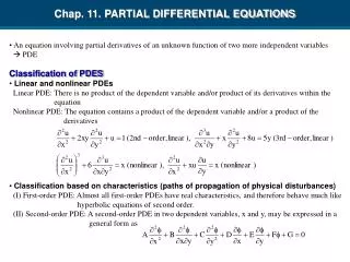
Partial Differential Equations • An equation involving partial derivatives of an unknown function of two or more independent variables • The following are examples. Note: u depends on both x and y
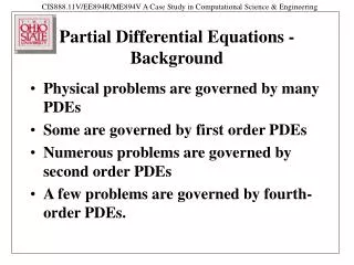
Partial Differential Equations • Because of their widespread application in engineering, our study of PDE will focus on linear, second-order equations • The following general form will be evaluated for B2 - 4AC
B2-4AC Category Example < 0 Elliptic Laplace equation (steady state with 2 spatial dimensions = 0 Parabolic Heat conduction equation (time variable with one spatial dimension >0 Hyperbolic Wave equation (time-variable with one spatial dimension
Scope of Lectures on PDE • Finite Difference: Elliptic • The Laplace Equation • Finite difference solution • Boundary conditions • Finite Difference: Parabolic • Heat conduction • Explicit method • Simple implicit method
Specific Study Objectives • Recognize the difference between elliptic, parabolic, and hyperbolic PDE • Recognize that the Liebmann method is equivalent to the Gauss-Seidel approach for solving simultaneous linear algebraic equations • Recognize the distinction between Dirichlet and derivative boundary conditions • Know the difference between convergence and stability of parabolic PDE • Apply finite difference to parabolic and elliptic PDE using various boundary conditions and step sizes
Finite Difference: Elliptic EquationsB2- 4AC < 0 • Typically used to characterize steady-state boundary value problems • Before solving, the Laplace equation will be solved from a physical problem
The Laplace Equation • Models a variety of problems involving the potential of an unknown variable • We will consider cases involving thermodynamics, fluid flow, and flow through porous media
The Laplace Equation • Let’s consider the case of a plate heated from the boundaries • How is this equation derived from basic concepts of continuity? • How does it relate to flow fields?
Consider the plate below, with thickness Dz. The temperatures are known at the boundaries. What is the temperature throughout the plate? T = 400 T = 200 T= 200 T = 200
First, recognize how the shape can be set in an x-y coordinate system T = 400 y T = 200 T= 200 T = 200 x
T = 400 y T= 200 T = 200 x Divide into a grid, with increments by Dx and Dy T = 200
T = 400 y T= 200 T = 200 x What is the temperature here, if using a block centered scheme? T = 400 y T = 200 T= 200 x
T = 400 y T= 200 T = 200 x What is the temperature here, if using a grid centered scheme? T = 200
Consider the element shown below on the face of a plate Dz in thickness. The plate is illustrated everywhere but at its edges or boundaries, where the temperature can be set. y D y x D x
q(y + D y) q(x + D x) q(x) Consider the steady state heat flux q in and out of the elemental volume. q(y) By continuity, the flow of heat in must equal the flow of heat out.
Dividing by Dx, Dy, Dz and D t : As x & y approach zero, the equation reduces to: Again, this is our continuity equation
Equation A The link between flux and temperature is provided by Fourier’s Law of heat conduction Equation B where qi is the heat flux in the direction i. Substitute B into A to get the Laplace equation
Equation A Equation B
Consider Fluid Flow In fluid flow, where the fluid is a liquid or a gas, the continuity equation is: The link here can by either of the following sets of equations: The potential function: Stream function:
Flow in Porous Media Darcy’s Law The link between flux and the pressure head is provided by Darcy’s Law
Poisson Equation For a case with sources and sinks within the 2-D domain, as represented by f(x,y), we have the Poisson equation. Now let’s consider solution techniques.
Evaluate these equations based on the grid and central difference equations (i,j+1) (i,j) (i+1,j) (i-1,j) (i,j-1)
(i,j+1) (i,j) (i+1,j) (i-1,j) (i,j-1) If D x = D y we can collect the terms to get:
(i,j+1) (i,j) (i+1,j) (i-1,j) (i,j-1) This equation is referred to as the Laplacian difference equation. It can be applied to all interior points. We must now consider what to do with the boundary nodes.
Boundary Conditions • Dirichlet boundary conditions: u is specified at the boundary • Temperature • Head • Neumann boundary condition: the derivative is specified • qi • Combination of both u and its derivative (mixed boundary condition)
The simplest case is where the boundaries are specified as fixed values. This case is known as the Dirichlet boundary conditions. u2 u1 u3 u4
Consider how we can deal with the lower node shown, u1,1 u2 Note: This grid would result in nine simultaneous equations. u1 1,2 u3 1,1 2,1 u4 -4u1,1 +u1,2+u2,1+u1 +u4 = 0
Let’s consider how to model the Neumann boundary condition centered finite divided difference approximation y (200,100) h = 0.05x + 100 (0,100) x (0,0) (200,0) suppose we wanted to consider this end grid point
The two boundaries are consider to be symmetry lines due to the fact that the BC translates in the finite difference form to: h i+1,j = h i-1,j and h i,j+1 = h i,j-1 1,2 1,1 2,1
h1,1 = (2h1,2 + 2 h2,1)/4 h1,2 = (h1,1 + h1,3+2h22)/4 2,2 1,2 1,1 2,1
Example The grid on the next slide is designed to solve the LaPlace equation Write the finite difference equations for the nodes (1,1), (1,2), and (2,1). Note that the lower boundary is a Dirichlet boundary condition, the left boundary is a Neumann boundary condition, and Dx = Dy.
Strategy • Resolve the governing equation as a finite difference equation • Resolve the boundary conditions as finite difference equations • Apply the governing equation at each node • At boundary nodes, include the finite difference estimation of the boundary
The Liebmann Method • Most numerical solutions of the Laplace equation involves systems that are much larger that the general system we just evaluated • Note that there are a maximum of five unknown terms per line • This results in a significant number of terms with zero’s
The Liebmann Method • In addition to the fact that they are prone to round-off errors, using elimination methods on such sparse system waste a great amount of computer memory storing zeros • Therefore, we commonly employ approaches such as Gauss-Seidel, which when applied to PDEs is also referred to as Liebmann’s method.
The Liebmann Method • In addition the equations will lead to a matrix that is diagonally dominant. • Therefore the procedure will converge to a stable solution. • Over relaxation is often employed to accelerate the rate of convergence
As with the conventional Gauss Seidel method, the iterations are repeated until each point falls below a pre-specified tolerance:
y (200,100) h = 0.05x + 100 (0,100) x (0,0) (200,0) Modeling 1/2 of the system shown, we can develop the following schematic where Dx = Dy = 20 m The finite difference equations can be solved using a a spreadsheet. This next example is part of the PDE example you can download from my homepage.
CAN USE EXCEL DEMONSTRATION You will get an error message in Excel that state that it will not resolve a circular reference.
After selecting the appropriate command, EXCEL with perform the Liebmann method for you. In fact, you will be able to watch the iterations.
Assuming K = 5 m/day, we can calculate the q’s • Use centered differences, for example @ cell B2 • qx = -K h/x = -(5m/d) (102.6m-101.6m) /(2*20m) = -0.125 m/d • qy = -K h/y = -(5m/d) (101 m-102.7 m) /(2*20m) = 0.2125 m/d ...end of problem.
Secondary Variables • Because its distribution is described by the Laplace equation, temperature is considered to be the primary variable in the heated plate problem • A secondary variable may also be of interest • In this case, the second variable is the rate of heat flux across the place surface
Secondary Variables FINITE DIFFERENCE APPROXIMATION BASED ON RESULTS OF TEMPERATURE DISTRIBUTION
The Resulting Flux Is A Vector With Magnitude And Direction Note: qis in degrees If qx=0, qis 90 or 270 depending on whether qy is positive or negative, respectively