Download
1 / 24
300 likes | 791 Vues
Understand the uses of theodolite in surveying, including measuring angles, ranging curves, and setting out grades. Learn about centring, transiting, and other essential terminology in theodolite surveying. Follow step-by-step instructions for temporary adjustments and measuring horizontal angles accurately.

E N D
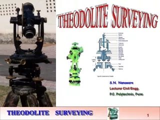
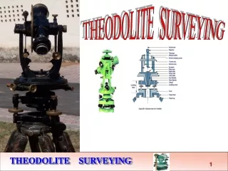
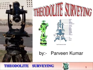
THEODOLITE TRAVERSING BY S N Nanaware Visit for more Learning Resources
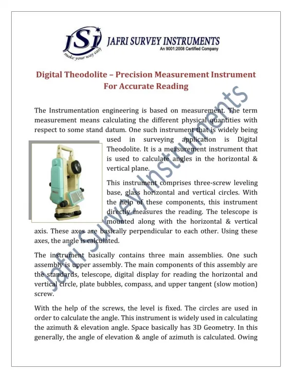
INTRODUCTION • The system of surveying in which the angles are measured with the help of a theodolite, is called Theodolite surveying. • Theodolite is used to measure the horizontal and vertical angles. • Theodolite is more precise than magnetic compass. • Magnetic compass measures the angle up to as accuracy of 30’. However a vernier theodolite measures the angles up to and accuracy of 10’’, 20”. • There are variety of theodolite vernier, optic, electronic etc.
USES OF THEODOLITE • Measuring horizontal and vertical angles • Locating points on a line • Prolonging survey lines • Finding difference of level • Setting out grades • Ranging curves • Tachometric Survey • Magnetic bearing (W.C.B.) measurement
DEFINITION • Centring • The process of setting about the theodolite exactly over the station mark is known as centring. • Transiting • The process of turning the telescope about its horizontal axis in a vertical plane through 180ᵒ is termed as transiting. • Face left • If the vertical circle of the instrument is on the left side of the observer while taking a reading ,the position is called the face left. • Face right • If the vertical circle of the instrument is on the right side of the observer while taking a reading ,the position is called the face right
DEFINITION • Changing face • It is an operation of bringing the face of the telescope form left to right and vice versa. • Swinging the telescope • It is the process of turning the telescope in horizontal plane. • Vertical axis • The vertical axis is the axis about which the instrument can be rotation in a horizontal plane. • Line of collimation • It is an imaginary line passing through the intersection of the cross hairs at the diaphragm and the optical centre of the object glass and its continuation. • Axis of the plate level • It is the straight line tangential to the longitudinal curve of plate tube at its centre.
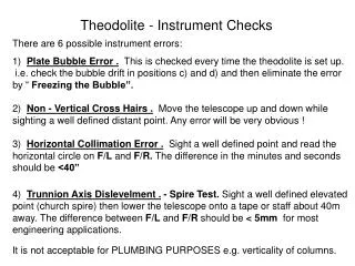
TEMPORARY ADJUSTMENT OF THEODOLITE • Before setting up the theodolite, it should be ensured that • The levelling screws are at the centre of their run. • The shifting head of the theodolite is at its centre so that equal movement is possible in all the direction. • The wing nuts on the tripod legs are tripod enough so that when raised, the tripod legs do not fall under their own weight.
TEMPORARY ADJUSTMENT OF THEODOLITE • Such adjustments involve the following steps • Setting up • Centring • Levelling up • Focusing the eye-piece • Focussing the object glass • Elimination of parallax
MEASURING HORIZONTAL ANGLE A B • Ordinary Method To measure horizontal angle AOB • Set up the theodolite at station point O and level it accurately. • Set the vernier A to the zero or 3600 of thehorizontal circle. Tighten the upper clamp. θ • Loosen the lower clamp. Turn the instrument and direct the telescope towards A to bisect it accurately with the use of tangent screw. After bisecting accurately check the reading which must still read zero. Read the vernier B and record both the readings. o • Loosen the upper clamp and turn the telescope clockwise until line of sight bisects point B on the right hand side. Then tighten the upper clamp and bisect it accurately by turning its tangent screw.
MEASURING HORIZONTAL ANGLE A B • Read both verniers. The reading of the vernier a which was initially set at zero gives the value of the angle AOB directly and that of the other vernier B by deducting 1800 .The mean of the two vernier readings gives the value of the required angle AOB. • Change the face of the instrument and repeat the whole process. The mean of the two vernier readings gives the second value of the angle AOB which should be approximately or exactly equal to the previous value. • The mean of the two values of the angle AOB ,one with face left and the other with face right ,gives the required angle free from all instrumental errors. θ o
MEASURING HORIZONTAL ANGLE • There are two methods of measuring horizontal angles. • Repetition method • Reiteration method • Repetition method • This method is used for very accurate work. In this method ,the same angle is added several times mechanically and the correct value of the angle is obtained by dividing the accumulated reading by the no. of repetitions. • The No. of repetitions made usually in this method is six, three with the face left and three with the face right .In this way ,angles can be measured to a finer degree of accuracy than that obtainable with the least count of the vernier.
MEASURING HORIZONTAL ANGLE • Set up the theodolite at starting point O and level it accurately. A B • To measure horizontal angle by repetitions method • Measure The horizontal angle AOB. θ₃ • Loosen the lower clamp and turn the telescope clock – wise until the object (A) is sighted again. Bisect B accurately by using the upper tangent screw. The verniers will now read the twice the value of the angle now. θ₂ θ₁ • Repeat the process until the angle is repeated the required number of times (usually 3). Read again both verniers . The final reading after n repetitions should be approximately n X (angle). Divide the sum by the number of repetitions and the result thus obtained gives the correct value of the angle AOB. o • Change the face of the instrument. Repeat exactly in the same manner and find another value of the angle AOB. The average of two readings gives the required precise value of the angle AOB. • The face of the instrument is chang and the previous procedure is followed.
MEASURING HORIZONTAL ANGLE • Reiteration method • This method is another precise and comparatively less tedious method of measuring the horizontal angles. • It is generally preferred when several angles are to be measured at a particular station. • This method consists in measuring several angles successively and finally closing the horizon at the starting point. The final reading of the vernier A should be same as its initial reading.
MEASURING HORIZONTAL ANGLE A B • To measure horizontal angle by reiteration method • Set up the instrument over station point O and level it accurately. • Direct the telescope towards point A which is known as referring object. Bisect it accurately and check the reading of vernier as 0 or 3600 . Loosen the lower clamp and turn the telescope clockwise to sight point B exactly. Read the verniers again and The mean reading will give the value of angle AOB. • Similarly bisect C & D successively, read both verniers at Procedure. each bisection, find the value of the angle BOC and COD. • Finally close the horizon by sighting towards the referring object (point A). o C D
MEASURING HORIZONTAL ANGLE A B • The vernier A should now read 3600. If not note down the error .This error occurs due to slip etc. • If the error is small, it is equally distributed among the several angles .If large the readings should be discarded and a new set of readings be taken. o C D
MEASURING VERTICAL ANGLE • To Measure the Vertical Angle of an object A at a station O • Set up the theodolite at station point O and level it accurately with reference to the altitude bubble. • Set the zero of vertical vernier exactly to the zero of the vertical circle clamp and tangent screw. • Bring the bubble of the altitude level in the central position by using clip screw. The line of sight is thus made horizontal and vernier still reads zero. • Loosen the vertical circle clamp screw and direct the telescope towards the object A and sight it exactly by using the vertical circle tangent screw. • Read both verniers on the vertical circle, The mean of the two vernier readings gives the value of the required angle. • Change the face of the instrument and repeat the process. The mean of of the two vernier readings gives the second value of the required angle. • The average of the two values of the angles thus obtained, is the required value of the angle free from instrumental errors.
COMPUTATION OF LATITUDE AND DEPARTURE • Latitude(L) • The latitude of a line is its orthographic projection on the N-S axis representing the meridian. Thus, the latitude of a line is the distance measured parallel to the North-South line. • Thus, Latitude(L)=l cosθ • Departure(D) • The departure of a line is its orthographic projection on the axis perpendicular to the meridian. The perpendicular axis is also known as the E-W axis. • Thus, departure(D)= l sinθ
Consecutive coordinates • The latitude and departure of a point calculated with reference to preceding point are said to be the consecutive coordinates of that point. • Independent coordinates • The coordinates of any point with respect to a common origin are called the independent coordinates of that point. The origin may be a station of the traverse or a point entirely outside the traverse.
BALANCING OF TEAVERSE • A traverse is balanced by applying corrections to latitudes and departures. This is called balancing a traverse. • The following are common methods of adjusting a traverse • Bowditch's rule • Transit rule • Third rule • Graphical construction method
TRAVERSE AREA • The coordinates method For more detail contact us