Download
1 / 28
281 likes | 369 Vues
Explore theoretical tensile strength, stress concentrations, crack loading modes, and Griffith theory in fracture mechanics. Understand stress intensity factors, sharp cracks, and crack growth under various loads. Dive into Von Mises criterion for plastic zone analysis.

E N D
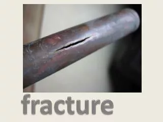
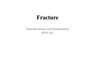
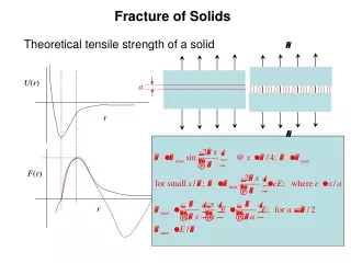
Fracture of Solids Theoretical tensile strength of a solid U(r) a r F(r) r
Fracture of Solids Work of fracture F(r) a 2g r Work of fracture for a defect-free solid
Stress Concentrations Airy stress function a
Elliptical flaw Def: Stress Concentration factor, Kt The radius of curvature at a is, 2b so 2a for Stress Concentrations For the circular flaw
Stress field of an Elliptical flaw y ao x bo ao is the ellipse defined by the flaw. 2a The Cartesian coordinates, x, y are connected to the elliptical coordinates a, b by a b
Stress field of an Elliptical flaw r is the distance along y = 0. The relative values of r/a and b/a compared to 1 determine the behavior of and define regions of interest. In the region r/a < 1 the leading term (dominant) including the bluntness contribution of b/ais, r < a As b/a 0 (a sharp “crack”) the stress field decays as (a/r)1/2. In the region, r/a >1 and the stress field scales as (a/r)2
Def: Stress Intensity Factor, K Sharp Cracks 2a Central crack of length 2a in an infinite plate under uniform tension. The leading terms for r <<a,
Sharp Cracks The stress intensity factor defines the strength of the crack in much the same way as the Burgers vector defines the strength of a dislocation.
Crack Loading Modes Mode III: Out-of plane or longitudinal shear Mode I: Opening Mode II: In-plane shear
MPa Units of K Y = numerical factor depending on geometry and loading
Sharp Cracks Mode I stress field Cartesian coordinates Cylindrical polar coordinates
Sharp Cracks Mode II stress field Cartesian coordinates Mode III stress field Cartesian coordinates
2(a+da) da da 2a Griffith theory of fracture Consider a crack of length 2a in a 2D plate of infinite extent under external boundary tractions. The total energy, UT of the system is composed of 3 terms. Here U load is the work done by the applied loads Ti on the system. We will subsequently show that
The surface energy of the crack system is The total energy may now be written as U a* a Griffith theory of fracture For a thin plate under load the excess elastic energy in the system owing to the presence of the crack is,
Griffith theory of fracture We can find the position of the energy for fracture, corresponding to the maximum in UT, For the case of plain strain
Def: Crack extension force Griffith theory of fracture G is the (negative) change of potential energy per unit crack extension per unit width. Energy/area = Force/length
2(a+da) da da 2a Griffith theory of fracture Mechanical work during crack extension Apply tractions loading the crack system During crack extension the work done is
Griffith theory of fracture Mechanical work during crack extension The elastic energy at location 3 is just The change in elastic energy is just Then
Griffith theory of fracture Plane Strain We can rearrange this to read What is a “typical value” of K at which fracture of a brittle solid is predicted E ~ 1011 Pa, g ~ 1Jm-2 Many materials exhibit critical K values 10 -100 times larger then this. Why?
Def: Crack extension force a P D a+da Crack extension force mg Crack growth under fixed load
Def: Crack extension force a a+da Crack extension force P D Crack growth under fixed displacement
Crack growth under fixed displacement Crack extension force Crack growth under fixed load
At edge of plastic zone 1st estimate of the plastic zone radius
Reminder: Mode I Stress Intensity Factor y (x2) r q x (x1) z (x3)
Von Mises criterion(It helps to obtain principal stresses, first)
Principal stresses Identify elastic-plastic boundary, r(q) Substitute these stresses into Von Mises criterion & solve for r as function of q where
y 1.0 x 1.0 SIZE & SHAPE OF THE PLASTIC ZONE PLANE STRESS r(q)/ry PLANE STRAIN r(q)/ry